HEIGHT CONTROL SENSOR INSTALLATION

-
INSTALL REAR HEIGHT CONTROL SENSOR SUB-ASSEMBLY LH
-
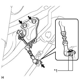
Text in Illustration *1 Matchmark Install the height control sensor with the 2 bolts.
- Torque:
- 13 N*m { 133 kgf*cm, 10 ft.*lbf }
Note
Replace the rear height control sensor sub-assembly with a new one if it is dropped.
-
Align the matchmarks on the link and bracket.
-
Connect the sensor link with the nut.
- Torque:
- 5.6 N*m { 57 kgf*cm, 50 in.*lbf }
-
Connect the connector, and then attach the connector.
-
Attach the clamp.
-
-
INSTALL REAR HEIGHT CONTROL SENSOR SUB-ASSEMBLY RH
Tech Tips
Use the same procedure described for the LH side.
-
INSTALL REAR WHEEL
- Torque:
- 112 N*m { 1142 kgf*cm, 83 ft.*lbf }
-
CONNECT CABLE TO NEGATIVE BATTERY TERMINAL
Note
When disconnecting the cable, some systems need to be initialized after the cable is reconnected Click here.
-
ADJUST VEHICLE HEIGHT
Note
-
While adjusting vehicle height, do not put anyone or anything on or in the vehicle because doing so will affect vehicle height.
-
Height control sensors are installed on both the left and right sides. However, each side cannot be adjusted individually, as the left and right sides are not controlled independently.
-
Even if the height control sensor of only one side is adjusted, the vehicle height of both the left and right sides will change.
-
Suspend vehicle height control by pressing the height control switch.
-
Put the vehicle on a level surface.
-
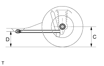
Measure the vehicle height (C - D measurement) on the right side and left side.
Standard vehicle height (See page Click here) Difference between right and left side 10 mm (0.394 in.) or less -
If the actual vehicle height differs from the vehicle height (C - D measurement), adjust it by jacking up the frame, etc. (Procedure "A").
-
If the procedure "A" differs from the vehicle height (C - D measurement), adjust it by following the procedures below.
-
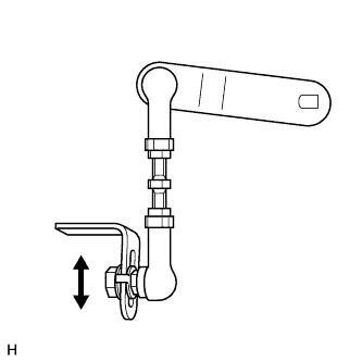
Loosen the nut.
-
Move the height control sensor link up and down along the slotted hole of the bracket.
-
Adjust the vehicle height to the vehicle height (C - D measurement) while checking the value on the intelligent tester or voltmeter.
Standard voltage 2.5 V -
Tighten the nut.
- Torque:
- 5.6 N*m { 57 kgf*cm, 50 in.*lbf }
-
-
If the vehicle height cannot be adjusted by performing procedure "A", adjust it again by following the procedures below.
-
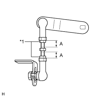
Text in Illustration *1 Lock Nut Loosen the 2 lock nuts of the height control sensor link.
-
Adjust the vehicle height to the vehicle height (C - D measurement) by turning the link while checking the value on the intelligent tester or the voltmeter.
Standard voltage 2.5 V Tech Tips
The vehicle height will be changed by approximately 3.0 mm (0.118 in.) when changing the link by approximately 2 mm (0.0787 in.).
-
Tighten the 2 lock nuts.
- Torque:
- 5.4 N*m { 55 kgf*cm, 48 in.*lbf }
-
-
Check that the lengths of the screw parts, labeled "A" in the illustration, are within the standard values.
Standard Length Item Specified Condition LH 6.0 to 12.5 mm (0.24 to 0.49 in.) RH 6.5 to 15.0 mm (0.26 to 0.59 in.) -
Change the vehicle height (from the normal position to the high position, and from the high position to the normal position).
-
Measure the vehicle height (C - D measurement) on the right and left side (Procedure "D").
-
Check if the vehicle height (C - D measurement) is within the specified range.
Tech Tips
If the values are outside the standard range, perform the procedures from procedure "A" to procedure "D" again.
-