KINETIC DYNAMIC SUSPENSION SYSTEM, Diagnostic DTC:C1831/31, C1832/32

| DTC Code | DTC Name |
|---|---|
| C1831/31 | Accumulator Solenoid Malfunction / Upside |
| C1832/32 | Accumulator Solenoid Malfunction / Downside |
DESCRIPTION
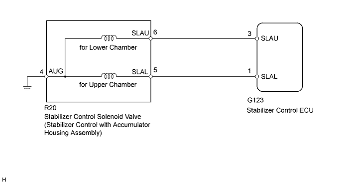
The stabilizer control ECU receives information from the steering angle sensor, skid control ECU (speed signal) and yaw rate and acceleration sensor via CAN communication. Based on this information, the stabilizer control ECU turns the stabilizer control solenoid valve (built into the stabilizer control with accumulator housing assembly) on or off.
| DTC Code | DTC Detection Condition | Trouble Area |
|---|---|---|
| C1831/31 C1832/32 |
Either condition is met:
|
|
WIRING DIAGRAM
INSPECTION PROCEDURE
PROCEDURE
-
READ VALUE USING INTELLIGENT TESTER (ACCUMULATOR VALVE)
-
Turn the ignition switch off.
-
Connect the intelligent tester to the DLC3.
-
Turn the ignition switch to ON.
-
Turn the intelligent tester on.
-
Enter the following menus: Chassis / KDSS / Data List.
-
Select the item below in the Data List, and read the value displayed on the intelligent tester.
KDSS Tester Display Measurement Item/Range Normal Condition Diagnostic Note Accumulator Valve (Downside) Stabilizer control solenoid valve (for Lower Chamber)/
ON or OFF
ON: Stabilizer control solenoid valve closed
OFF: Stabilizer control solenoid valve open
- Accumulator Valve (Upside) Stabilizer control solenoid valve (for Upper Chamber)/
ON or OFF
ON: Stabilizer control solenoid valve open
OFF: Stabilizer control solenoid valve closed
- -
Perform the Active Test of the stabilizer control ECU using the intelligent tester.
KDSS Tester Display Test Part Control Range Diagnostic Note Accumulator Valve (Upside) Stabilizer control solenoid valve (for Upper Chamber) Valve ON / OFF The operating sound of the solenoid (clicking sound) can be heard
ON: Data List ON
OFF: Data List OFF
When the Active Test is performed, the solenoid turns on for 3 seconds.
Accumulator Valve (Downside) Stabilizer control solenoid valve (for Lower Chamber) Valve ON / OFF The operating sound of the solenoid (clicking sound) can be heard
ON: Data List ON
OFF: Data List OFF
When the Active Test is performed, the solenoid turns on for 3 seconds.
-
Check that the solenoid operating sound can be heard, and that the Data List display changes between ON and OFF in response to the Active Test.
OK Solenoid operating sound can be heard and display changes between ON and OFF in response to Active Test.
NG 
CHECK HARNESS AND CONNECTOR (STABILIZER CONTROL ECU - STABILIZER CONTROL SOLENOID VALVE) Click here
OK 
-
-
RECONFIRM DTC
-
Clear the DTCs Click here
-
Check for DTCs Click here.
Result Result Proceed to DTC is output A DTC is not output B
B 
USE SIMULATION METHOD TO CHECK Click here
A 
REPLACE STABILIZER CONTROL ECU Click here
-
-
CHECK HARNESS AND CONNECTOR (STABILIZER CONTROL ECU - STABILIZER CONTROL SOLENOID VALVE)
-
Disconnect the stabilizer control ECU connector.
-
Disconnect the Stabilizer control with accumulator housing assembly connector.
-
Measure the resistance according to the value(s) in the table below.
Standard Resistance Tester Connection Condition Specified Condition G123-3 (SLAU) - R20-6 (SLAU) Always Below 1 Ω G123-3 (SLAU) - Body ground Always 10 kΩ or higher G123-1 (SLAL) - R20-5 (SLAL) Always Below 1 Ω G123-1 (SLAL) - Body ground Always 10 kΩ or higher R20-4 (AUG) - Body ground Always Below 1 Ω
NG
REPAIR OR REPLACE HARNESS OR CONNECTOR
OK
-
-
INSPECT STABILIZER CONTROL SOLENOID VALVE
-
Disconnect the Stabilizer control with accumulator housing assembly connector.
-
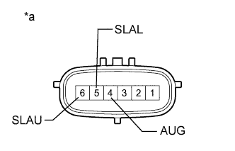
Text in Illustration *a Component without harness connected
(Stabilizer Control with Accumulator Housing Assembly)
Measure the resistance according to the value(s) in the table below.
Standard Resistance C1831/31 (for Upper Chamber) Tester Connection Condition Specified Condition 5 (SLAL) - 4 (AUG) 25°C (77°F) 24.3 to 25.7 Ω C1832/32 (for Lower Chamber) Tester Connection Condition Specified Condition 6 (SLAU) - 4 (AUG) 25°C (77°F) 24.3 to 25.7 Ω -
Check for an operating sound of the stabilizer control solenoid valve.
-
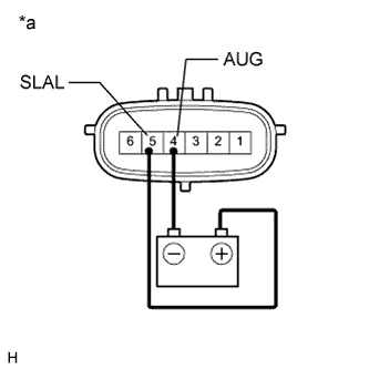
Text in Illustration *a Component without harness connected
(Stabilizer Control with Accumulator Housing Assembly)
for Upper Chamber:
Connect terminal 5 (SLAL) to the positive (+) battery terminal, and terminal 4 (AUG) to the negative (-) battery terminal.
OK An operating sound (click sound) can be heard. -
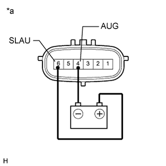
Text in Illustration *a Component without harness connected
(Stabilizer Control with Accumulator Housing Assembly)
for Lower Chamber:
Connect terminal 6 (SLAU) to the positive (+) battery terminal, and terminal 4 (AUG) to the negative (-) battery terminal.
OK An operating sound (click sound) can be heard.
-
NG
REPLACE STABILIZER CONTROL WITH ACCUMULATOR HOUSING ASSEMBLY Click here
OK
REPLACE STABILIZER CONTROL ECU Click here
-