AIR SUSPENSION SYSTEM TERMINALS OF ECU

-
CHECK SUSPENSION CONTROL ECU
Tech Tips
-
Inspect the connectors from the back side while the connectors are connected.
-
Check the operation of a particular valve by listening for an operating sound or by using the Data List.
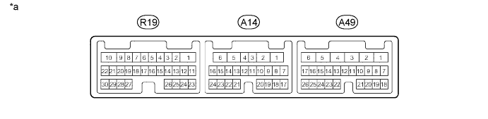
Text in Illustration *a Component with harness connected
(Suspension Control ECU)
- - Terminal No. (Symbol) Wiring Color Terminal Description Condition Specified Condition R19-9 (SLEX) - Body ground LG Exhaust valve Exhaust valve not operating Below 1 V Exhaust valve operating 8 V or higher R19-10 (GND) - Body ground W-B Ground Always Below 1 Ω R19-13 (SBR2) - Body ground R Rear height control sensor RH power source Ignition switch ON 4.5 to 5.5 V R19-14 (SBL2) - Body ground R Rear height control sensor LH power source Ignition switch ON 4.5 to 5.5 V R19-15 (SGL2) - Body ground V Rear height control sensor LH ground Always Below 1 Ω R19-16 (SGR2) - Body ground W Rear height control sensor RH ground Always Below 1 Ω R19-22 (RC) - Body ground G AIR SUS relay Compressor motor not operating Below 1 V Compressor motor operating 8 V or higher R19-24 (SHRL) - Body ground GR Rear height control sensor LH Vehicle being raised Voltage increases within range of 0.5 to 4.5 V in proportion to vehicle height Vehicle being lowered Voltage decreases within range of 0.5 to 4.5 V in proportion to vehicle height R19-26 (SHRR) - Body ground W Rear height control sensor RH Vehicle being raised Voltage increases within range of 0.5 to 4.5 V in proportion to vehicle height Vehicle being lowered Voltage decreases within range of 0.5 to 4.5 V in proportion to vehicle height R19-27 (SHR2) - Body ground B Height control sensor (for AFS ECU) Vehicle being raised Voltage increases within range of 0.5 to 4.5 V in proportion to vehicle height Vehicle being lowered Voltage decreases within range of 0.5 to 4.5 V in proportion to vehicle height A14-9 (SBR) - Body ground G-B Front acceleration sensor RH power source Ignition switch ON 4.5 to 5.5 V A14-10 (SGR) - Body ground L-Y Front acceleration sensor RH ground Always Below 1 Ω A14-15 (SLRL) - Body ground L Gate solenoid valve (No. 2 height control valve) Ignition switch ON Below 1 V Engine idling, button of height control switch is pushed from "down" to "up" 8 V or higher A14-16 (SLRR) - Body ground V Leveling solenoid valve (No. 2 height control valve) Ignition switch ON Below 1 V Engine idling, button of height control switch is pushed from "down" to "up" 8 V or higher A14-17 (RM-) - Body ground G Motor lock (-) Always Below 1 Ω A14-18 (SGFR) - Body ground R-L Front acceleration sensor RH Ignition switch ON 0.5 to 4.5 V A14-19 (RM+) - Body ground P Motor lock (+) Engine idling, vehicle height changes from N to HI by pressing height control switch (While height control compressor assembly operating) Below 1 V A14-21 (SGL) - Body ground W Height control sensor ground (for AFS ECU) Always Below 1 Ω A14-22 (SBL) - Body ground R-G Height control sensor power source (for AFS ECU) Ignition switch ON 4.5 to 5.5 V A49-1 (IG) - Body ground B IG power supply Ignition switch ON 11 to 14 V A49-3 (B) - Body ground GR Battery power supply Always 11 to 14 V A49-5 (GND) - Body ground W-B Ground Always Below 1 Ω A49-7 (CANH) - A49-8 (CANL) R*1 - W CAN communication line Ignition switch off 54 to 69 Ω GR*2 - W A49-13 (TD) - Body ground L Height control OFF switch
-
Ignition switch ON
-
Switch pressed and held
11 to 14 V
-
Ignition switch ON
-
Switch not pressed
Below 1 V A49-14 (DNSW) - Body ground V Height control switch "down" side
-
Ignition switch ON
-
Switch pressed and held
11 to 14 V
-
Ignition switch ON
-
Switch not pressed
Below 1 V A49-15 (UPSW) - Body ground P Height control switch "up" side
-
Ignition switch ON
-
Switch pressed and held
11 to 14 V
-
Ignition switch ON
-
Switch not pressed
Below 1 V A49-16 (SGR3) - Body ground R Rear acceleration sensor ground Always Below 1 Ω A49-17 (SBR3) - Body ground W Rear acceleration sensor power source Ignition switch ON 4.5 to 5.5 V A49-22 (TSW2) - Body ground B Absorber control switch (COMF)
-
Ignition switch ON
-
Absorber control switch set to NORMAL
10 to 14 V
-
Ignition switch ON
-
Absorber control switch set to COMF
Below 1.5 V A49-23 (TSW1) - Body ground G Absorber control switch (SPORT)
-
Ignition switch ON
-
Absorber control switch set to NORMAL
10 to 14 V
-
Ignition switch ON
-
Absorber control switch set to SPORT
Below 1.5 V A49-26 (SGRR) - Body ground LG Rear acceleration sensor Ignition switch ON 0.5 to 4.5 V
-
*1: for RHD
-
*2: for LHD
-