MANUAL TRANSMISSION UNIT (for 1KD-FTV) REASSEMBLY

-
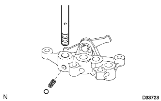
INSTALL NO. 1 RELEASE ARM
-
Install the release arm and shift arm pivot to the interlock bracket.
-
Install a new E-ring to the shift arm pivot.
-
-
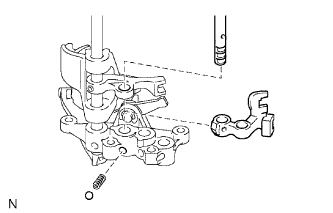
INSTALL NO. 4 GEAR SHIFT FORK SHAFT
-
Install the compression spring and shift detent ball to the interlock bracket.
-
Install the No. 4 shift fork shaft.
-
-
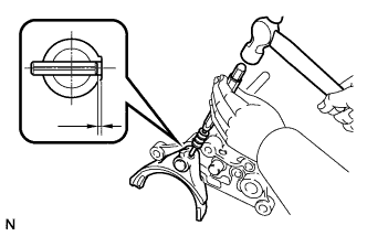
INSTALL NO. 4 GEAR SHIFT FORK
-
Install the No. 4 shift fork to the No. 4 shift fork shaft.
-
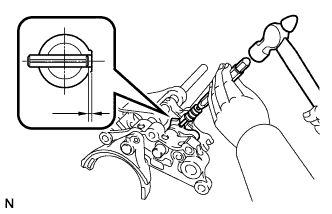
Using 5 mm a pin punch and hammer, tap a new slotted pin into the No. 4 shift fork and No. 4 shift fork shaft.
Standard depth 0 to 0.5 mm (0 to 0.0196 in.)
-
-
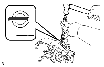
INSTALL NO. 1 GEAR SHIFT FORK
-
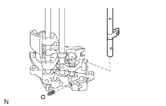
Install the No. 1 shift fork and No. 2 shift head to the No. 4 shift fork shaft.
-
Using a 5 mm pin punch and hammer, tap a new slotted pin into the No. 2 shift head and No. 4 shift fork shaft.
Standard depth 0 to 0.5 mm (0 to 0.0196 in.)
-
-
INSTALL NO. 1 GEAR SHIFT FORK SHAFT
-
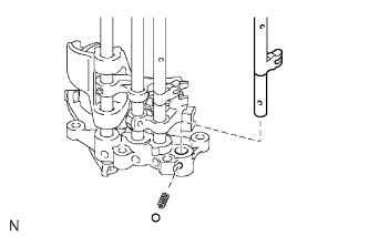
Install the compression spring and shift detent ball to the interlock bracket.
-
Install the No. 1 shift fork shaft to the interlock bracket.
-
-
INSTALL NO. 1 GEAR SHIFT HEAD
-
Install the No. 1 shift head to the No. 1 shift fork shaft.
-
Using a 5 mm pin punch and hammer, tap a new slotted pin into the No. 1 shaft head and No. 1 shift fork shaft.
Standard depth 0 to 0.5 mm (0 to 0.0196 in.)
-
-
INSTALL NO. 2 GEAR SHIFT FORK SHAFT
-
Install the compression spring and shift detent ball to the interlock bracket.
-
Install the No. 2 shift fork shaft to the interlock bracket.
-
-
INSTALL NO. 2 GEAR SHIFT FORK
-
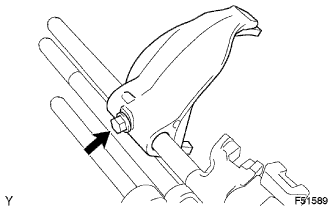
Install the No. 2 shift fork with a new bolt.
- Torque:
- 20 N*m { 199 kgf*cm, 14 ft.*lbf }
-
-
INSTALL NO. 3 GEAR SHIFT FORK SHAFT
-
Install the compression spring and shift detent ball to the interlock bracket.
-
Install the No. 3 shift fork shaft to the interlock bracket.
-
-
INSTALL NO. 3 GEAR SHIFT FORK
-
Install the No. 3 shift fork with a new bolt.
- Torque:
- 20 N*m { 199 kgf*cm, 14 ft.*lbf }
-
-
INSTALL TRANSMISSION CASE NEEDLE BEARING
-
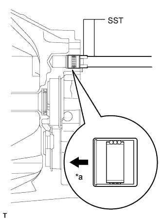
Text in Illustration *a Front Using SST, install the bearing to the front transmission case.
- SST
- 09950-60010 ( 09951-00220 )
- 09950-70010 ( 09951-07100 )
-
-
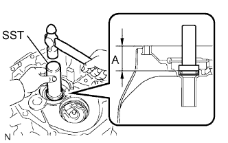
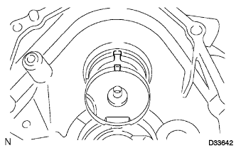
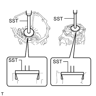
INSTALL TRANSMISSION CASE OIL SEAL
-
Using SST and a hammer, tap a new oil seal into the front transmission case so that dimension A in the illustration is as specified.
- SST
- 09950-70010 ( 09951-07100 )
- 09950-60010 ( 09951-00470 )
Dimension A 60.0 to 60.8 mm (2.362 to 2.394 in.) -
Apply gear oil to the lip of the oil seal.
-
-
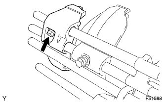
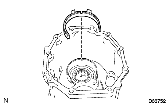
INSTALL FRONT BEARING SHAFT SNAP RING
-
Using snap ring pliers, install the 2 snap rings.
-
-
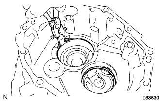
INSTALL NO. 3 OIL RECEIVER PIPE
-
Install the No. 3 oil receiver pipe to the front transmission case.
Tech Tips
Align the protrusion of the oil receiver pipe with the cutout of the transmission case and install the oil receiver pipe to the front transmission case.
-
-
INSTALL FRONT TRANSMISSION CASE
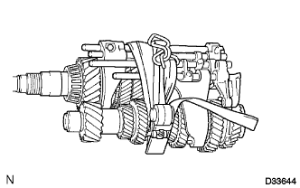
-
Apply gear oil to all sliding and rotating parts.
-
Temporarily install the output shaft, input shaft, counter gear shaft and control assembly, and tie them with a piece of rope or string.
-
Using a snap ring expander, expand the 2 snap rings and install the output shaft, input shaft, counter gear shaft and control assembly.
Tech Tips
Make sure that the snap ring fits into the grooves of the input shaft and front bearing of the counter gear shaft.
-
Untie the output shaft, input shaft, counter gear shaft and control assembly.
-
Using a 27 mm hexagon wrench, install the plug to the front transmission case.
- Torque:
- 39 N*m { 400 kgf*cm, 29 ft.*lbf }
-
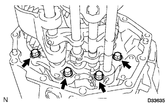
Install the interlock bracket with the 4 bolts.
- Torque:
- 21 N*m { 214 kgf*cm, 15 ft.*lbf }
-
-
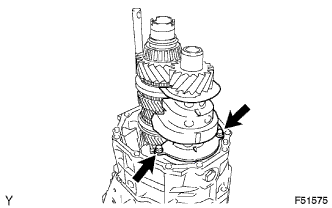
INSTALL REVERSE IDLER GEAR
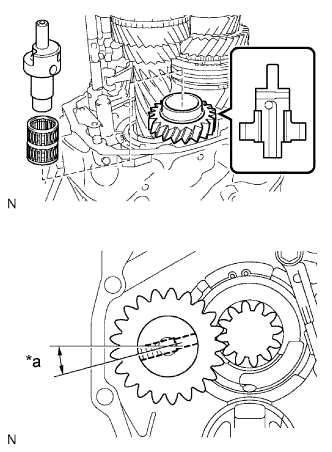
Text in Illustration *a 15°
-
Install the reverse idler gear, reverse idler gear bearing and reverse idler gear shaft.
Tech Tips
Make sure that the reverse idler gear faces the correct direction as shown in the illustration.
Note
Make sure that the hole in the reverse idler shaft is in the position shown in the illustration.
-
-
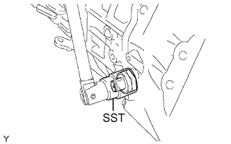
INSTALL BACK-UP LIGHT SWITCH ASSEMBLY
-
Using SST, install a new gasket and the back-up light switch to the front transmission case.
- SST
- 09817-16011
- Torque:
- 44 N*m { 449 kgf*cm, 32 ft.*lbf }
-
-
INSTALL SHIFT AND SELECT LEVER
-
Install the spring and lock ball pin to the shift and select lever.
-
Install the select lever, select cam and interlock plate to the lever shaft.
-
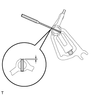
Using a 5 mm pin punch and hammer, tap in the straight pin to the lever shaft.
Standard depth 1.0 to 2.0 mm (0.0394 to 0.0787 in.) -
Install a new bolt to the shift and select lever.
- Torque:
- 47 N*m { 479 kgf*cm, 35 ft.*lbf }
-
Install a new E-ring to the lever shaft.
-
-
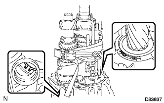
INSTALL SHIFT AND SELECT LEVER SHAFT
-
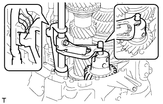
Align the groove of the shift and select cam with the reverse idler shaft and the claw with the groove of the control assembly, and then install the shift and select lever shaft.
-
-
INSTALL NO. 2 OIL RECEIVER PIPE
-
Install the No. 2 oil receiver pipe to the transmission middle case.
-
-
INSTALL DRAIN PLUG SUB-ASSEMBLY
-
Install a new gasket and the drain plug to the transmission middle case.
- Torque:
- 37 N*m { 377 kgf*cm, 27 ft.*lbf }
-
-
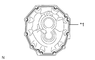
INSTALL TRANSMISSION MIDDLE CASE
-
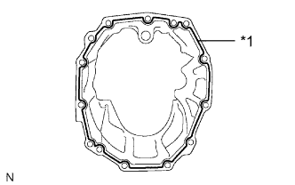
Apply seal packing to the transmission middle case as shown in the illustration.
Seal Packing Toyota Genuine Seal Packing 1281, Three Bond 1281 or equivalent Text in Illustration *1 Seal Packing Note
Parts must be assembled within 10 minutes of application. Otherwise, the seal packing (FIPG material) must be removed and reapplied.
-
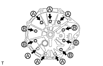
Install the transmission middle case with the 11 bolts.
- Torque:
- 40 N*m { 408 kgf*cm, 30 ft.*lbf }
Bolt length for bolt A: 40 mm (1.57 in.) for bolt B: 80 mm (3.15 in.)
-
-
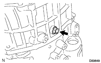
INSTALL REVERSE IDLER GEAR SHAFT BOLT
-
Install a new gasket and the reverse idler gear shaft bolt to the reverse idler gear shaft.
- Torque:
- 28 N*m { 286 kgf*cm, 21 ft.*lbf }
-
-
INSTALL TRANSMISSION OIL SEPARATOR
-
Install the transmission oil separator with the 2 bolts.
- Torque:
- 8.5 N*m { 87 kgf*cm, 75 in.*lbf }
-
-
INSTALL TRANSFER ADAPTER NEEDLE ROLLER BEARING
-
Text in Illustration *a Front Using SST, install the bearing to the transfer adapter.
- SST
- 09950-60010 ( 09951-00220 )
- 09950-70010 ( 09951-07150 )
-
-
INSTALL COUNTER GEAR REAR RADIAL BALL BEARING
-
Coat a new counter gear rear radial ball bearing with gear oil, and then using SST and a press, install it to the transfer adapter.
- SST
- 09950-70010 ( 09951-07360 )
- 09950-60010 ( 09951-00650 )
-
Install the bearing lock plate with the bolt.
- Torque:
- 11 N*m { 115 kgf*cm, 8 ft.*lbf }
-
-
INSTALL REAR OUTPUT SHAFT BEARING
-
Using SST and a press, press in 2 new rear output shaft bearings (outer race) to the transfer adapter.
- SST
- 09950-70010 ( 09951-07100, 09951-07360 )
- 09950-60020 ( 09951-00790 )
-
-
INSTALL TRANSFER ADAPTER CASE PLUG
-
Install the case plug to the transfer adapter.
- Torque:
- 35 N*m { 357 kgf*cm, 26 ft.*lbf }
-
-
INSTALL OIL SEPARATOR PACKING SEAL
-
Install the oil separator packing seal to the transfer adapter.
Tech Tips
Insert the protruding part of the oil separator packing seal into the groove of the transfer adapter.
-
-
INSTALL NO. 1 OIL RECEIVER PIPE
-
Install the No. 1 oil receiver pipe to the transfer adapter.
-
-
INSTALL MANUAL TRANSMISSION FILLER PLUG
-
Install 2 new gaskets and the 2 transmission filler plugs to the transfer adapter.
- Torque:
- 37 N*m { 377 kgf*cm, 27 ft.*lbf }
-
-
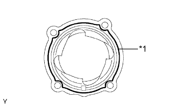
INSTALL TRANSFER ADAPTER
Text in Illustration *1 Seal Packing
-
Apply seal packing to the transfer adapter as shown in the illustration.
Seal packing Toyota Genuine Seal Packing 1281, Three Bond 1281 or equivalent Note
Parts must be assembled within 10 minutes of application. Otherwise, the seal packing (FIPG material) must be removed and reapplied.
-
Install the transfer adapter and 2 brackets to the transmission case with the 10 bolts.
- Torque:
- 40 N*m { 408 kgf*cm, 30 ft.*lbf }
-
-
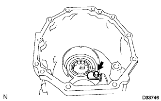
INSTALL SHIFT DETENT BALL PLUG
-
Install the ball and compression spring to the transfer adapter.
-
Install a new shift detent ball plug to the transfer adapter.
- Torque:
- 25 N*m { 250 kgf*cm, 18 ft.*lbf }
-
-
INSTALL MANUAL TRANSMISSION OUTPUT SHAFT REAR SET NUT
-
Using a belt and wooden block, securely fasten the transmission to the workbench.
-
Install a new output shaft spacer and a new rear output shaft bearing.
-
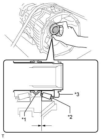
Text in Illustration *1 Output Shaft Spacer *2 Rear Output Shaft Bearing *3 Manual Transmission Output Shaft Rear Set Nut Temporarily install a new rear set nut by hand.
Tech Tips
Fit the spacer and rear output shaft bearing securely.
-
Move the shift and select lever shaft to N.
-
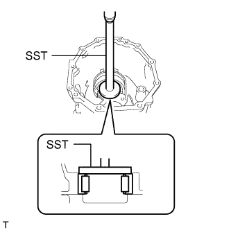
Using SST, rotate the output shaft 15 times at a speed of 100 rpm or less in order to settle the bearing.
-
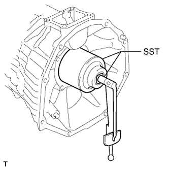
Using SST and a torque wrench, measure the output shaft preload.*1
- SST
- 09326-35010 ( 09326-03010, 09326-03020 )
-
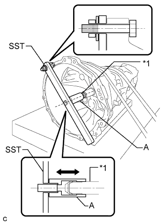
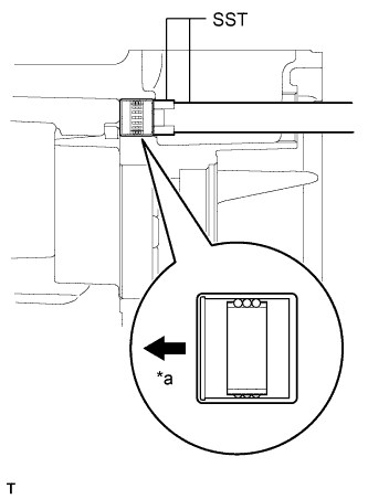
Text in Illustration *1 Input Shaft Engage 5th gear, and then secure the input shaft using SST.
- SST
- 09322-35010 ( 09322-03010, 09322-03020, 09322-03030, 90105-12087, 90170-12030, 94622-51200 )
Tech Tips
-
Install SST securely so that (A) is in-line with the input shaft.
-
Make sure that (A) moves back and forth by hand after installing SST.
-
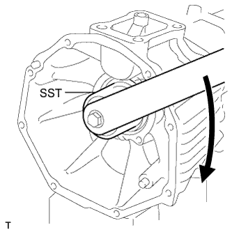
Using SST and a torque wrench, tighten the nut.
- Torque:
- 580 N*m { 5914 kgf*cm, 428 ft.*lbf }
-
Move the shift and select lever shaft to N.
-
Using SST, rotate the output shaft 15 times at a speed of 100 rpm or less in order to settle the bearing.
-
Using SST and a torque wrench, measure the output shaft preload.*2
- SST
- 09326-35010 ( 09326-03010, 09326-03020 )
-
Adjust the preload so that the difference between *1 and *2 is within the specified range.
Standard Preload (at starting) *2 - *1 = 0.45 to 1.05 N*m (4.59 to 10.7 kgf*cm, 3.98 to 9.29 in.*lbf)
-
If the preload is more than the standard, replace the output shaft spacer.
-
-
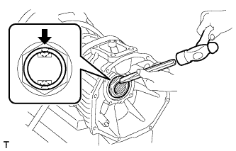
Using a chisel and hammer, caulk the rear set t nut.
-
-
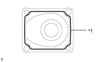
INSTALL MANUAL TRANSMISSION CASE COVER
Text in Illustration *1 Seal Packing
-
Apply seal packing to the transmission case cover as shown in the illustration.
Seal packing Toyota Genuine Seal Packing 1281, Three Bond 1281 or equivalent Note
Parts must be assembled within 10 minutes of application. Otherwise, the seal packing (FIPG material) must be removed and reapplied.
-
Install the transmission case cover with the 4 bolts.
- Torque:
- 18 N*m { 184 kgf*cm, 13 ft.*lbf }
-
-
INSTALL SHIFT LEVER HOUSING
-
Install the shift lever housing with the bolt.
- Torque:
- 47 N*m { 479 kgf*cm, 35 ft.*lbf }
-
-
INSTALL FLOOR SHIFT CONTROL SHIFT LEVER RETAINER SUB-ASSEMBLY
Text in Illustration *1 Seal Packing
-
Apply seal packing to the floor shift control shift lever retainer as shown in the illustration.
Seal packing Toyota Genuine Seal Packing 1281, Three Bond 1281 or equivalent Note
Parts must be assembled within 10 minutes of application. Otherwise, the seal packing (FIPG material) must be removed and reapplied.
-
Install the floor shift control shift lever retainer with the 4 bolts.
- Torque:
- 20 N*m { 204 kgf*cm, 15 ft.*lbf }
-
-
INSTALL CLUTCH RELEASE FORK SUPPORT BOOT
-
Install the support boot to the front transmission case.
-
-
INSTALL RELEASE FORK SUPPORT
-
Install the release fork support to the manual transmission unit.
- Torque:
- 39 N*m { 400 kgf*cm, 29 ft.*lbf }
-
-
INSTALL CLUTCH RELEASE BEARING ASSEMBLY
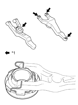
Text in Illustration *1 Release hub grease
-
Apply release hub grease to the clutch release bearing, and then install it to the clutch release fork with the clip.
Grease Toyota Genuine Release Hub Grease or equivalent
-
-
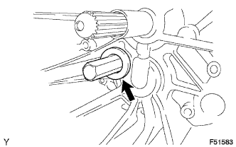
INSTALL CLUTCH RELEASE FORK SUB-ASSEMBLY
-
Install the clutch release fork.
Note
After the installation, move the fork forward and backward to check that the release bearing slides smoothly.
-
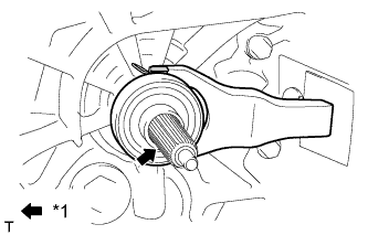
Text in Illustration *1 Clutch spline grease Apply clutch spline grease to the spline of the input shaft.
Grease Toyota Genuine Clutch Spline Grease or equivalent
-