MANUAL TRANSMISSION UNIT (for 1GR-FE) DISASSEMBLY

-
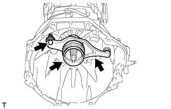
REMOVE CLUTCH RELEASE FORK SUB-ASSEMBLY
-
Remove the clutch release fork with the clutch release bearing from the transmission unit.
-
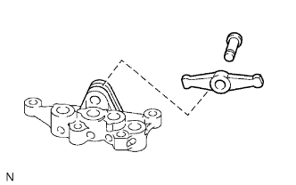
Remove the release fork support from the transmission unit.
-
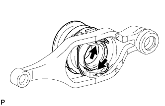
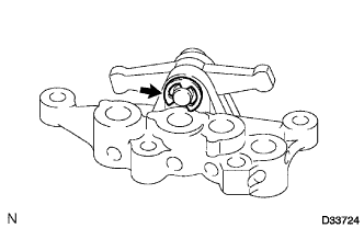
Remove the clip and clutch release bearing from the clutch release fork.
-
-
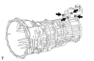
REMOVE FLOOR SHIFT CONTROL SHIFT LEVER RETAINER SUB-ASSEMBLY
-
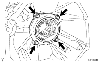
Remove the 4 bolts.
-
Using a plastic-faced hammer, remove the floor shift control shift lever retainer.
-
-
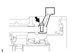
REMOVE SHIFT LEVER HOUSING
-
Remove the bolt and shift lever housing.
-
-
REMOVE MANUAL TRANSMISSION CASE COVER
-
Remove the 4 bolts and transmission case cover.
-
-
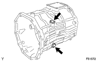
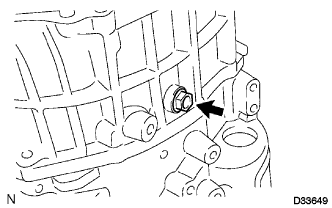
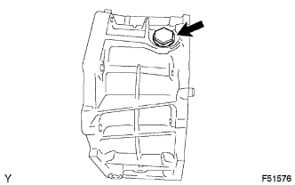
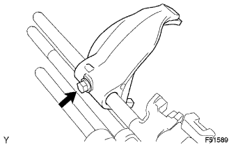
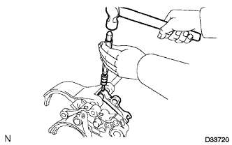
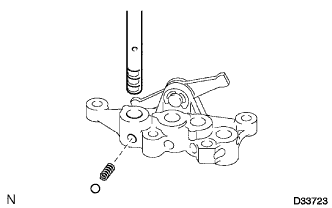
REMOVE SHIFT DETENT BALL PLUG
-
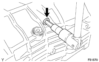
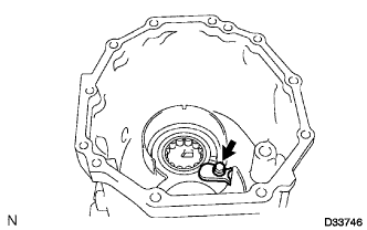
Using a 10 mm hexagon socket wrench, remove the shift detent ball plug from the transfer adapter.
-
Remove the ball and compression spring from the transfer adapter.
-
-
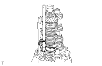
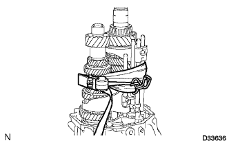
REMOVE MANUAL TRANSMISSION OUTPUT SHAFT REAR SET NUT
-
Using a belt and wooden block, securely fasten the transmission to the workbench.
-
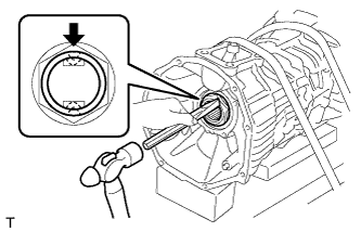
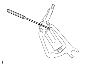
Using a chisel and hammer, unstake the rear set nut.
-
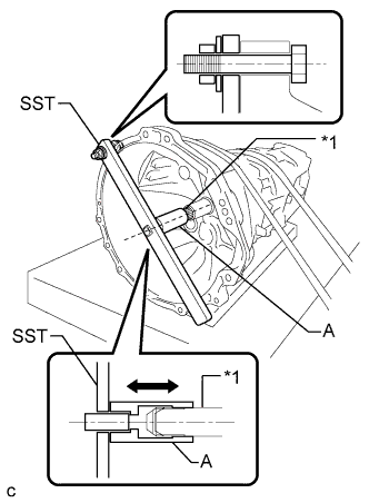
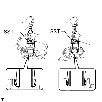
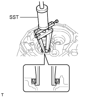
Text in Illustration *1 Input Shaft Engage 5th gear, and then secure the input shaft using SST.
- SST
- 09322-35010 ( 09322-03010, 09322-03020, 09322-03030, 90105-12087, 90170-12030, 94622-51200 )
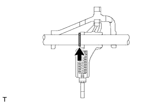
Tech Tips
-
Install SST securely so that the part labeled A is in-line with the input shaft.
-
Make sure that the part labeled A moves back and forth by hand after installing SST.
-
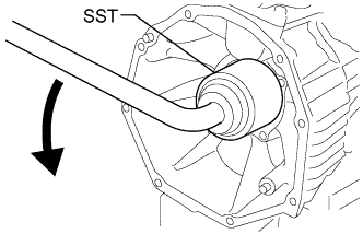
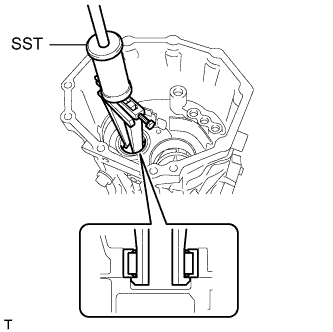
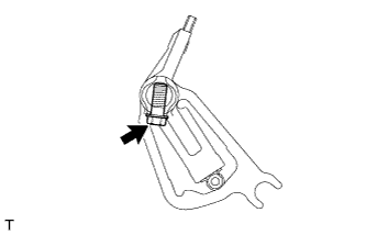
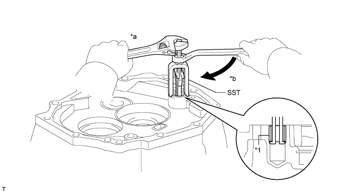
Using an L-type handle and SST, remove the rear set nut from the output shaft.
- SST
- 09326-35010 ( 09326-03010 )
-
Remove the belt and wooden block from the transmission.
-
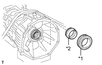
Text in Illustration *1 Output Shaft Bearing *2 Output Shaft Spacer Remove the output shaft bearing and spacer.
-
-
REMOVE TRANSFER ADAPTER
-
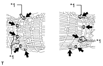
Remove the 10 bolts and 4 brackets.
Text in Illustration *1 Bracket -
Using a plastic-faced hammer, carefully tap off the transfer adapter to remove it.
Tech Tips
Place a brass bar against the rib portion of the case.
-
-
REMOVE MANUAL TRANSMISSION FILLER PLUG
-
Remove the 2 transmission filler plugs and 2 gaskets from the transfer adapter.
-
-
REMOVE NO. 1 OIL RECEIVER PIPE
-
Remove the No. 1 oil receiver pipe from the transfer adapter.
-
-
REMOVE OIL SEPARATOR PACKING SEAL
-
Remove the oil separator packing seal from the transfer adapter.
-
-
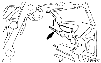
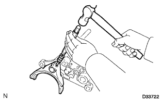
REMOVE TRANSFER ADAPTER CASE PLUG
-
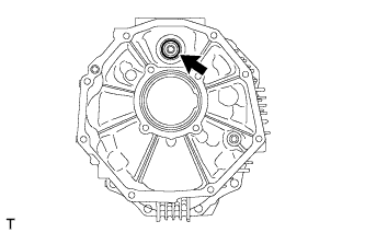
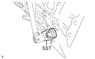
Using a 14 mm hexagon socket wrench, remove the case plug from the transfer adapter.
-
-
REMOVE REAR OUTPUT SHAFT BEARING
-
Using SST, remove the 2 rear output shaft bearings (outer race) from the transfer adapter.
- SST
- 09308-00010
-
-
REMOVE COUNTER GEAR REAR RADIAL BALL BEARING
-
Remove the bolt and bearing lock plate.
-
Using SST, remove the counter gear rear radial ball bearing from the transfer adapter.
- SST
- 09308-00010
-
-
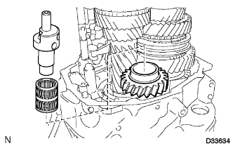
REMOVE TRANSFER ADAPTER NEEDLE ROLLER BEARING
-
Remove the roller bearing from the transfer adapter.
-
-
REMOVE TRANSMISSION OIL SEPARATOR
-
Remove the 2 bolts and oil separator.
-
-
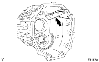
REMOVE REVERSE IDLER GEAR SHAFT BOLT
-
Remove the reverse idler gear shaft bolt and gasket from the reverse idler gear shaft.
-
-
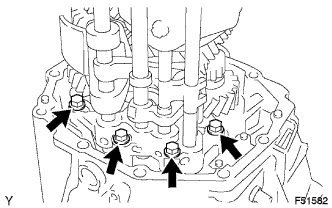
REMOVE TRANSMISSION MIDDLE CASE
-
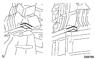
Text in Illustration *1 Bolt *2 Collar Remove the bolt and collar.
-
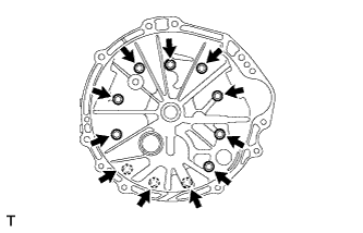
Remove the 11 bolts.
-
Using a plastic-faced hammer, carefully tap off the transmission middle case to remove it.
Tech Tips
Place a brass bar against the rib portion of the case.
-
-
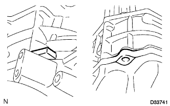
REMOVE DRAIN PLUG SUB-ASSEMBLY
-
Remove the drain plug and gasket from the transmission middle case.
-
-
REMOVE NO. 2 OIL RECEIVER PIPE
-
Remove the No. 2 oil receiver pipe from the transmission middle case.
-
-
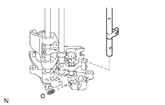
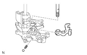
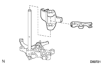
REMOVE SHIFT AND SELECT LEVER SHAFT
-
Remove the shift and select lever shaft from the reverse gear shaft.
-
-
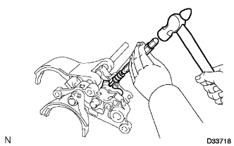
REMOVE SHIFT AND SELECT LEVER
-
Using a screwdriver, remove the E-ring.
-
Using a 5 mm pin punch and hammer, tap out the straight pin.
-
Remove the bolt, interlock plate, select cam and select lever from the lever shaft.
-
Remove the lock ball pin and spring from the shift and select lever.
-
-
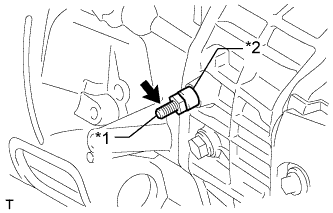
REMOVE BACK-UP LIGHT SWITCH ASSEMBLY
-
Using SST, remove the back-up light switch and gasket.
- SST
- 09817-16011
-
-
INSPECT REVERSE IDLER GEAR THRUST CLEARANCE
-
Using a feeler gauge, measure the thrust clearance.
Standard clearance 0.10 to 0.154 mm (0.00394 to 0.00606 in.) Maximum clearance 0.154 mm (0.00606 in.)
-
If the clearance is more than the maximum, replace the reverse idler gear shaft, reverse idler gear or transmission front case.
-
-
-
REMOVE REVERSE IDLER GEAR
-
Remove the reverse idler gear shaft, reverse idler gear bearing and reverse idler gear.
-
-
REMOVE FRONT TRANSMISSION CASE
-
Remove the 4 bolts and interlock bracket.
-
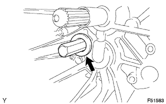
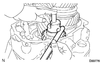
Using a 27 mm hexagon wrench, remove the case plug.
-
Tie the input shaft, counter gear and control assembly with a piece of rope or string.
-
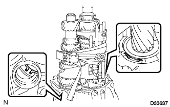
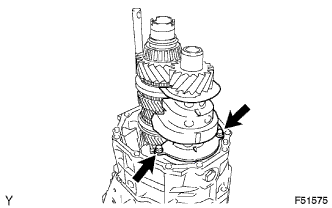
Expand the 2 snap rings and lift up the output shaft, input shaft, counter gear shaft and control assembly.
-
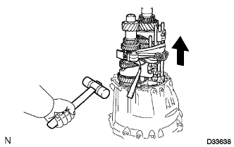
Remove the output shaft, input shaft, counter gear shaft and control assembly while gently tapping the clutch housing with a plastic-faced hammer.
Note
Take care not to subject the output shaft, input shaft, counter gear shaft and control assembly to any impact. This could cause the ball and spring to come out.
-
Separate the output shaft, input shaft, counter gear shaft and control assembly.
-
-
REMOVE NO. 3 OIL RECEIVER PIPE
-
Remove the No. 3 oil receiver pipe from the front transmission case.
-
-
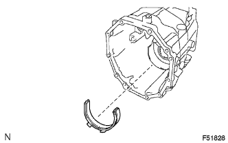
REMOVE FRONT BEARING SHAFT SNAP RING
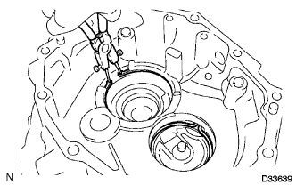
-
Using snap ring pliers, remove the 2 snap rings.
-
-
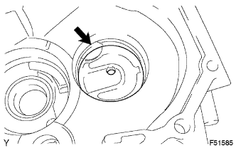
REMOVE TRANSMISSION CASE OIL SEAL
-
Using SST, remove the transmission case oil seal from the front transmission case.
- SST
- 09308-00010
-
-
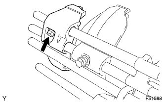
REMOVE TRANSMISSION CASE NEEDLE BEARING
-
Using SST, remove the bearing from the front transmission case.
Text in Illustration *1 Transmission Case Needle Bearing - - *a Hold *b Turn
-
-
REMOVE NO. 3 GEAR SHIFT FORK
-
Remove the bolt and No. 3 gear shift fork.
-
-
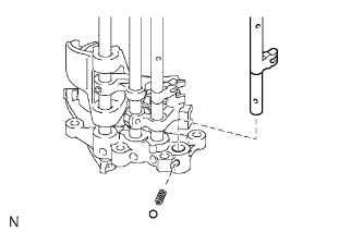
REMOVE NO. 3 GEAR SHIFT FORK SHAFT
-
Remove the No. 3 shift fork shaft, shift detent ball and compression spring.
-
-
REMOVE NO. 2 GEAR SHIFT FORK
-
Remove the bolt and No. 2 gear shift fork.
-
-
REMOVE NO. 2 GEAR SHIFT FORK SHAFT
-
Remove the No. 2 shift fork shaft, shift detent ball and compression spring.
-
-
REMOVE NO. 1 GEAR SHIFT FORK SHAFT
-
Using a 5 mm pin punch and hammer, tap out the slotted pin.
-
Remove the No. 1 shift fork shaft, shift detent ball, compression spring and No. 1 shift head.
-
-
REMOVE NO. 1 GEAR SHIFT FORK
-
Using a 5 mm pin punch and hammer, tap out the slotted pin.
-
Remove the No. 2 shift head and No. 1 shift fork.
-
-
REMOVE NO. 4 GEAR SHIFT FORK
-
Using a 5 mm pin punch and hammer, tap out the slotted pin.
-
Remove the No. 4 shift fork.
-
-
REMOVE NO. 4 GEAR SHIFT FORK SHAFT
-
Remove the No. 4 shift fork shaft, shift detent ball and compression spring.
-
-
REMOVE NO. 1 RELEASE ARM
-
Using a screwdriver, remove the E-ring.
-
Remove the shift arm pivot and release arm.
-