MANUAL TRANSMISSION ASSEMBLY (for 1KD-FTV) INSTALLATION

-
INSTALL TRANSFER ASSEMBLY
-
for 1KD-FTV:
Install the transfer assembly with the 8 bolts and 2 brackets.
- Torque:
- 24 N*m { 245 kgf*cm, 18 ft.*lbf }
Note
Take care not to damage the adaptor rear oil seal with the transfer input gear spline.
-
except 1KD-FTV:
Install the transfer assembly with the 8 bolts and bracket.
- Torque:
- 24 N*m { 245 kgf*cm, 18 ft.*lbf }
Note
Take care not to damage the adaptor rear oil seal with the transfer input gear spline.
-
-
INSTALL DIFFERENTIAL PRESSURE SENSOR ASSEMBLY (w/ DPF)
-
Install the differential pressure sensor assembly to the sensor bracket with the nut.
- Torque:
- 5.0 N*m { 51 kgf*cm, 44 in.*lbf }
-
-
INSTALL TRANSMISSION UPPER COVER SUB-ASSEMBLY
-
Install the upper cover with the 2 bolts.
- Torque:
- 12 N*m { 117 kgf*cm, 8 ft.*lbf }
-
-
INSTALL MANUAL TRANSMISSION WITH TRANSFER
-
Install the manual transmission with transfer with the 8 bolts.
- Torque:
- 72 N*m { 729 kgf*cm, 53 ft.*lbf }
-
-
CONNECT TRANSFER AND MANUAL TRANSMISSION BREATHER HOSE SUB-ASSEMBLY
-
w/o DPF:
-
Connect the 3 breather hoses.
-
Attach the breather hose clamp.
-
-
w/ DPF:
-
Connect the 3 breather hoses.
-
Attach the 2 breather hose clamps.
-
-
-
CONNECT WIRE HARNESS
-
w/o DPF:
-
Attach the 5 wire harness clamps.
-
Connect the 2 connector.
-
-
w/ DPF:
-
Attach the 8 wire harness clamps.
-
Connect the 3 connectors and 3 connector clamps.
-
-
-
INSTALL REAR NO. 1 ENGINE MOUNTING INSULATOR
-
Install the engine No. 1 mounting insulator rear with the 4 bolts.
- Torque:
- 65 N*m { 663 kgf*cm, 48 ft.*lbf }
-
-
INSTALL NO. 3 FRAME CROSSMEMBER SUB-ASSEMBLY
-
Install the No. 3 frame crossmember sub-assembly with the 4 bolts and 4 nuts.
- Torque:
- 72 N*m { 734 kgf*cm, 53 ft.*lbf }
-
Install the 4 bolts to the No. 3 frame crossmember sub-assembly.
- Torque:
- 30 N*m { 306 kgf*cm, 22 ft.*lbf }
-
-
INSTALL FRONT SUSPENSION MEMBER BRACKET LH
-
Install the front suspension member bracket LH with the 4 bolts.
- Torque:
- 33 N*m { 337 kgf*cm, 24 ft.*lbf }
-
-
INSTALL FRONT SUSPENSION MEMBER BRACKET RH
-
Install the front suspension member bracket RH with the 4 bolts.
- Torque:
- 33 N*m { 337 kgf*cm, 24 ft.*lbf }
-
-
CONNECT CLUTCH RELEASE CYLINDER ASSEMBLY
-
Connect the release cylinder with the 2 bolts.
- Torque:
- 12 N*m { 120 kgf*cm, 9 ft.*lbf }
-
Install a new clip to the flexible hose.
-
-
INSTALL STARTER ASSEMBLY
for 2.2 kW Type: Click here
for 2.7 kW Type: Click here
for 3.0 kW Type: Click here
-
INSTALL PROPELLER SHAFT ASSEMBLY
-
INSTALL FRONT PROPELLER SHAFT ASSEMBLY
-
INSTALL TRANSFER CASE LOWER PROTECTOR
-
Install the transfer case lower protector with the 4 bolts.
- Torque:
- 18 N*m { 184 kgf*cm, 13 ft.*lbf }
-
-
INSTALL FRONT EXHAUST PIPE ASSEMBLY
w/o DPF: Click here
w/ DPF: Click here
-
ADD MANUAL TRANSMISSION OIL
-
INSPECT MANUAL TRANSMISSION OIL
-
Park the vehicle on a level surface.
-
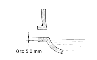
Check that the oil level is between 0 to 5 mm (0 to 0.196 in.) from the bottom lip of the filler plug opening.
-
If the result is not as specified, add transmission oil.
Note
-
Problems may occur when the oil level is too high or low.
-
After replacing the oil, drive the vehicle and check the oil level again.
-
-
Inspect for oil leaks when the oil level is low.
-
If the result is not as specified, add transmission oil.
-
-
Install a new gasket and the filler plug.
- Torque:
- 37 N*m { 377 kgf*cm, 27 ft.*lbf }
-
-
INSTALL FLOOR SHIFT SHIFT LEVER ASSEMBLY
-
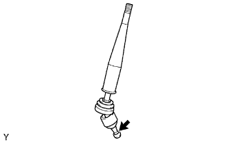
Apply MP grease to the tip of the shift lever.
Text in Illustration 
MP Grease -
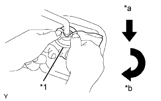
Text in Illustration *1 Cloth *a Down *b Clockwise Cover the shift lever cap with a cloth.
-
While pressing down on the shift lever cap, turn it clockwise to install the shift lever.
-
-
INSTALL NO. 1 SHIFT AND SELECT LEVER BOOT
-
Install the shift lever boot with the 4 screws.
-
-
INSTALL CONSOLE PANEL SUB-ASSEMBLY
-
Connect each connector.
-
Attach the 8 clips and 2 claws to install the console panel.
-
-
INSTALL SHIFT LEVER KNOB SUB-ASSEMBLY
-
CONNECT CABLE TO NEGATIVE BATTERY TERMINAL
Note
When disconnecting the cable, some systems need to be initialized after the cable is reconnected Click here.