OUTPUT SHAFT REASSEMBLY

-
INSTALL 3RD GEAR NEEDLE ROLLER BEARING
-
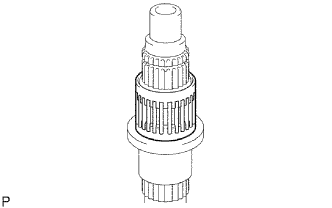
Coat the needle roller bearing with gear oil and install it to the output shaft.
-
-
INSTALL 3RD GEAR
-
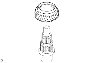
Coat the 3rd gear with gear oil and install it to the output shaft.
-
-
INSTALL NO. 1 SYNCHRONIZER RING
-
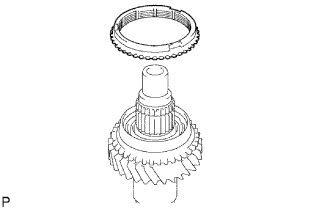
Coat the No. 1 synchronizer ring with gear oil and install it to the 3rd gear.
-
-
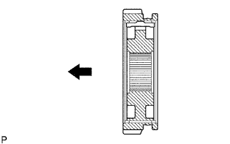
INSTALL NO. 2 TRANSMISSION CLUTCH HUB
-
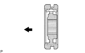
Coat the hub sleeve with gear oil and install it to the clutch hub.
Text in Illustration 
Front Note
Be sure to install the hub sleeve to the clutch hub in the correct direction.
-
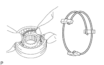
Install the 3 synchromesh shifting keys to the clutch hub with the 2 synchromesh shifting key springs.
Note
Do not set both openings of the shifting key springs in the same position.
-
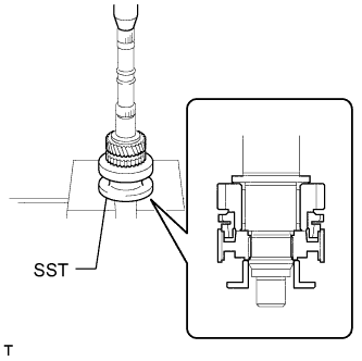
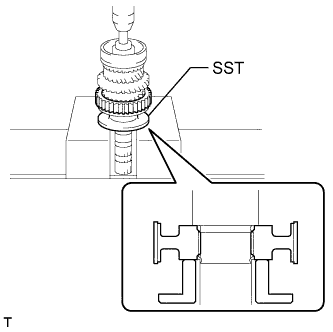
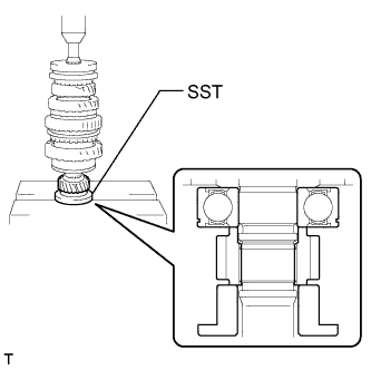
Using SST and a press, install the No. 2 clutch hub to the output shaft.
- SST
- 09316-60011 ( 09316-00021 )
-
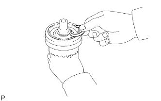
Select a clutch hub shaft snap ring that will allow minimal axial play.
Standard clearance 0.10 mm (0.00394 in.) or less Standard Clutch Hub Shaft Snap Ring Mark Thickness C-1 1.75 to 1.80 mm (0.0689 to 0.0709 in.) D 1.80 to 1.85 mm (0.0709 to 0.0728 in.) D-1 1.85 to 1.90 mm (0.0728 to 0.0748 in.) E 1.90 to 1.95 mm (0.0748 to 0.0768 in.) E-1 1.95 to 2.00 mm (0.0768 to 0.0787 in.) F 2.00 to 2.05 mm (0.0787 to 0.0807 in.) F-1 2.05 to 2.10 mm (0.0807 to 0.0827 in.) -
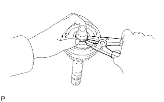
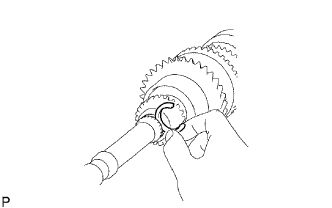
Using a snap ring expander, install the snap ring.
-
-
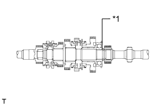
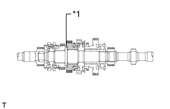
INSPECT 3RD GEAR THRUST CLEARANCE
-
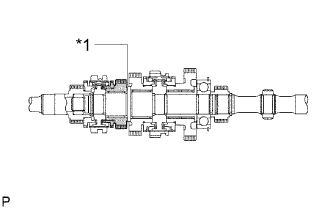
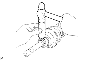
Text in Illustration *1 3rd Gear Using a feeler gauge, measure the thrust clearance.
Standard clearance 0.10 to 0.25 mm (0.00394 to 0.00984 in.)
-
If the result is not as specified, replace the No. 2 synchronizer ring set.
-
-
-
INSTALL 2ND GEAR NEEDLE ROLLER BEARING
-
Coat the needle roller bearing with gear oil and install it to the output shaft.
-
-
INSTALL 2ND GEAR
-
Coat the 2nd gear with gear oil and install it to the output shaft.
-
-
INSTALL NO. 2 SYNCHRONIZER RING (for 2nd Gear)
-
Coat the No. 2 synchronizer ring with gear oil and install it to the 2nd gear.
-
-
INSTALL NO. 1 TRANSMISSION CLUTCH HUB
-
Coat the reverse gear with gear oil and install it to the clutch hub.
Text in Illustration Front Note
Be sure to install the reverse gear to the clutch hub in the correct direction.
-
Install the 3 synchromesh shifting keys to the clutch hub with the 2 synchromesh shifting key springs.
Note
Do not set both openings of the shifting key springs in the same position.
-
Using SST and a press, install the clutch hub to the output shaft.
- SST
- 09316-60011
-
-
INSTALL NO. 1 SYNCHRONIZER RING (for 1st Gear)
-
Coat the synchronizer ring with gear oil and install it to the No. 1 clutch hub.
-
-
INSTALL 1ST GEAR BEARING INNER RACE LOCK BALL
-
Coat the lock ball with gear oil and install it to the output shaft.
-
-
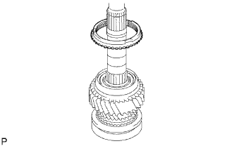
INSTALL 1ST GEAR BEARING INNER RACE
-
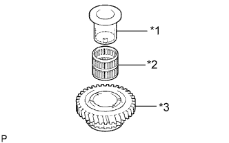
Text in Illustration *1 1st Gear Bearing Inner Race *2 1st Gear Needle Roller Bearing *3 1st Gear Coat the needle roller bearing with gear oil.
-
Install the inner race and needle roller bearing to the 1st gear.
-
-
INSTALL 1ST GEAR
-
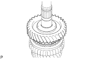
Coat the 1st gear with gear oil and install it to the output shaft.
-
-
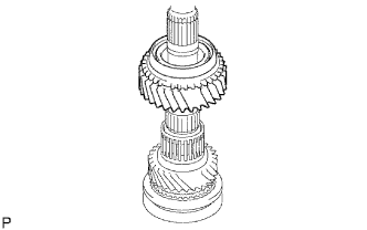
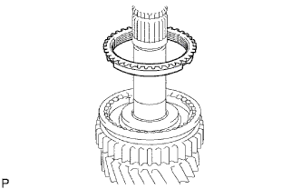
INSTALL OUTPUT SHAFT CENTER BEARING
-
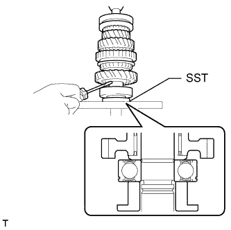
Using SST and a press, install the center bearing to the output shaft.
- SST
- 09316-60011 ( 09316-00021 )
-
-
INSPECT 1ST GEAR THRUST CLEARANCE
-
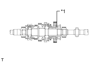
Text in Illustration *1 1st Gear Using a dial indicator, measure the thrust clearance.
Standard clearance 0.10 to 0.25 mm (0.00394 to 0.00984 in.)
-
If the result is not as specified, replace the No. 1 synchronizer ring set.
-
-
-
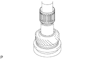
INSTALL 5TH GEAR
-
Using SST and a press, install the 5th gear to the output shaft.
- SST
- 09316-60011 ( 09316-00021 )
-
Select a snap ring that will allow minimal axial play.
Standard clearance 0.10 mm (0.00394 in.) or less Standard Output Shaft Bearing Shaft Snap Ring Mark Thickness A 2.67 to 2.72 mm (0.1052 to 0.1070 in.) B 2.73 to 2.78 mm (0.1075 to 0.1094 in.) C 2.79 to 2.84 mm (0.1099 to 0.1118 in.) D 2.85 to 2.90 mm (0.1123 to 0.1141 in.) E 2.91 to 2.96 mm (0.1146 to 0.1165 in.) F 2.97 to 3.02 mm (0.1170 to 0.1188 in.) G 3.03 to 3.08 mm (0.1193 to 0.1212 in.) H 3.09 to 3.14 mm (0.1217 to 0.1236 in.) J 3.15 to 3.20 mm (0.1241 to 0.1259 in.) K 3.21 to 3.26 mm (0.1264 to 0.1283 in.) L 3.27 to 3.32 mm (0.1288 to 0.1307 in.) -
Using a brass bar and hammer, tap on the snap ring.
-
-
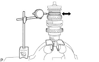
INSPECT 5TH GEAR THRUST CLEARANCE
-
Text in Illustration *1 5th Gear Using a dial indicator, measure the thrust clearance.
Standard clearance 0.10 to 0.30 mm (0.00394 to 0.0118 in.)
-
If the result is not as specified, replace the 5th gear.
-
-
-
INSPECT 3RD GEAR THRUST CLEARANCE
-
Text in Illustration *1 3rd Gear Using a feeler gauge, measure the thrust clearance.
Standard clearance 0.10 to 0.25 mm (0.00394 to 0.00984 in.)
-
If the result is not as specified, replace the No. 2 synchronizer ring set.
-
-
-
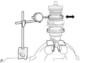
INSPECT 2ND GEAR THRUST CLEARANCE
-
Text in Illustration *1 2nd Gear Using a dial indicator, measure the thrust clearance.
Standard clearance 0.10 to 0.25 mm (0.00394 to 0.00984 in.)
-
If the result is not as specified, replace the No. 1 synchronizer ring set.
-
-
-
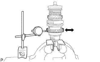
INSPECT 1ST GEAR THRUST CLEARANCE
-
Text in Illustration *1 1st Gear Using a dial indicator, measure the thrust clearance.
Standard clearance 0.10 to 0.25 mm (0.00394 to 0.00984 in.)
-
If the result is not as specified, replace the No. 1 synchronizer ring set.
-
-
-
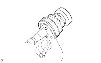
INSPECT 3RD GEAR RADIAL CLEARANCE
-
Using a dial indicator, measure the radial clearance.
Standard clearance 0.008 to 0.034 mm (0.000315 to 0.00133 in.)
-
If the result is not as specified, replace the 3rd gear needle roller bearing.
-
-
-
INSPECT 2ND GEAR RADIAL CLEARANCE
-
Using a dial indicator, measure the radial clearance.
Standard clearance 0.008 to 0.034 mm (0.000315 to 0.00133 in.)
-
If the result is not as specified, replace the 2nd gear needle roller bearing.
-
-
-
INSPECT 1ST GEAR RADIAL CLEARANCE
-
Using a dial indicator, measure the radial clearance.
Standard clearance 0.009 to 0.056 mm (0.000355 to 0.00220 in.)
-
If the result is not as specified, replace the 1st gear needle roller bearing.
-
-