MANUAL TRANSMISSION UNIT REASSEMBLY

-
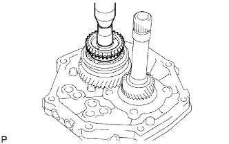
INSTALL OUTPUT SHAFT ASSEMBLY
-
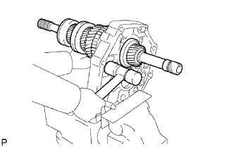
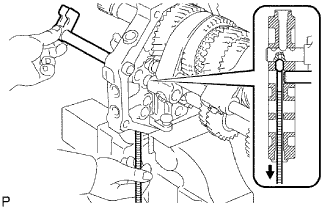
Install the output shaft to the intermediate plate by pushing on the output shaft and tapping on the intermediate plate with a plastic-faced hammer.
-
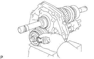
Using a snap ring expander, install the snap ring to the center bearing.
Tech Tips
Make sure the shaft snap ring is flush with the intermediate plate surface.
-
-
INSTALL INPUT SHAFT ASSEMBLY
-
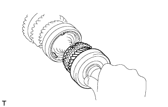
Coat the input shaft and No. 2 synchronizer ring with gear oil, and install them to the output shaft.
-
-
INSTALL COUNTER GEAR ASSEMBLY
-
Coat the input shaft and No. 2 synchronizer ring with gear oil.
-
Temporarily install the counter gear, input shaft and a new center bearing to the intermediate plate.
Note
Install the bearing (with snap ring) to the rear side of the counter gear.
-
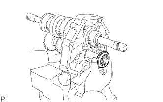
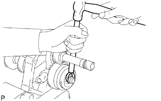
Using a plastic-faced hammer, install the center bearing to the intermediate plate by tapping the outer race to the counter gear center bearing.
Tech Tips
Hold the front side of the counter gear by hand.
-
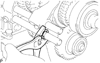
Using a snap ring expander, install the counter shaft center bearing snap ring to the counter shaft center bearing.
-
-
INSTALL OUTPUT SHAFT REAR BEARING RETAINER
-
Using a T40 "TORX" socket, install the output shaft rear bearing retainer to the intermediate plate with the 4 screws.
- Torque:
- 18 N*m { 184 kgf*cm, 13 ft.*lbf }
-
-
INSTALL REVERSE IDLER GEAR SUB-ASSEMBLY
-
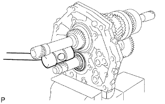
Install the reverse idler gear shaft and reverse idler gear to the intermediate plate.
-
Install the reverse idler gear shaft stopper to the intermediate plate with the bolt.
- Torque:
- 17 N*m { 173 kgf*cm, 13 ft.*lbf }
-
-
INSTALL REVERSE SHIFT ARM BRACKET
-
Install the reverse shift arm bracket to the intermediate plate with the 2 bolts.
- Torque:
- 18 N*m { 184 kgf*cm, 13 ft.*lbf }
-
-
INSTALL 5TH GEAR BEARING INNER RACE LOCK BALL
-
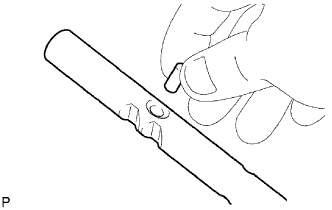
Install the lock ball.
-
-
INSTALL 5TH GEAR THRUST WASHER
-
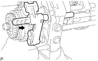
Install the 5th gear thrust washer.
-
-
INSTALL NO. 3 TRANSMISSION HUB SLEEVE
-
Coat the counter shaft 5th gear with gear oil.
-
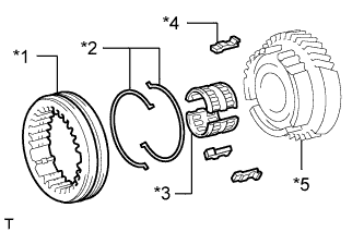
Install the counter 5th gear, counter shaft 5th gear bearing, 3 synchromesh shifting keys, 2 synchromesh shifting key springs and No. 3 transmission hub sleeve.
Text in Illustration *1 No. 3 Transmission Hub Sleeve *2 No. 3 Synchromesh Shifting Key Spring *3 Counter Shaft 5th Gear Bearing *4 No. 3 Synchromesh Shifting Key *5 Counter Shaft 5th Gear Tech Tips
Be sure to set the No. 3 transmission hub sleeve and 3 synchromesh shifting keys to the counter shaft 5th gear incorrect direction.
Text in Illustration 
Front
-
-
INSTALL COUNTER SHAFT 5TH GEAR
-
Install the counter 5th gear bearing to the 5th gear.
-
Install the counter shaft 5th gear to the counter gear.
-
Temporarily install the No. 1 synchronizer ring on the No. 5 gear spline piece.
-
Remove the intermediate plate from the vise.
-
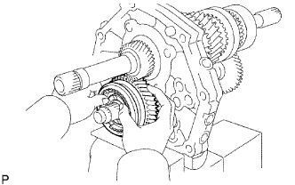
Stand the transmission as shown in the illustration.
-
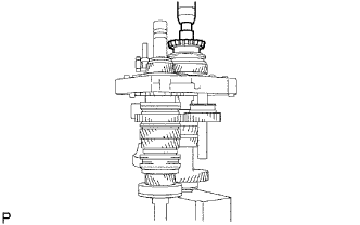
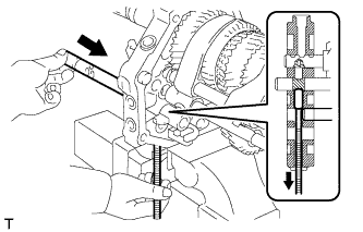
Using a press and 22 mm socket wrench, install the No. 5 gear spline piece with the No. 1 synchronizer ring slots aligned with the shifting keys.
-
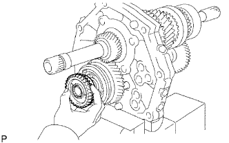
Fix the intermediate plate in a vise between aluminum plates.
-
Select a snap ring that will allow minimal axial play.
Standard clearance 0.10 mm (0.00394 in.) or less Standard Counter Gear Rear Shaft Snap Ring Mark Thickness A 2.80 to 2.85 mm (0.110 to 0.112 in.) B 2.85 to 2.90 mm (0.112 to 0.114 in.) C 2.90 to 2.95 mm (0.114 to 0.116 in.) D 2.95 to 3.00 mm (0.116 to 0.118 in.) E 3.00 to 3.05 mm (0.118 to 0.120 in.) F 3.05 to 3.10 mm (0.120 to 0.122 in.) G 3.10 to 3.15 mm (0.122 to 0.124 in.) -
Using a brass bar and hammer, tap the snap ring to the counter gear.
-
-
INSPECT COUNTER SHAFT 5TH GEAR THRUST CLEARANCE
-
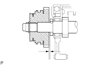
Using a feeler gauge, measure the counter shaft 5th gear thrust clearance.
Standard clearance 0.10 to 0.30 mm (0.00394 to 0.0118 in.)
-
If the result is not as specified, replace the counter shaft 5th gear.
-
-
-
INSTALL NO. 2 GEAR SHIFT FORK SHAFT
-
Install the No. 2 gear shift fork and No. 1 gear shift fork.
-
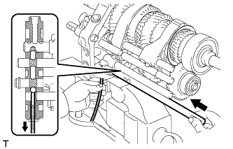
Pass the No. 2 gear shift fork shaft through the intermediate plate, No. 2 gear shift fork and No. 1 gear shift fork to install it.
-
Using a brass bar and hammer, tap the shaft snap ring onto the No. 2 gear shift fork shaft.
-
Install the bolt to the No. 2 gear shift fork.
- Torque:
- 20 N*m { 204 kgf*cm, 15 ft.*lbf }
-
-
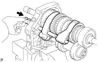
INSTALL NO. 2 SHIFT INTERLOCK PIN
-
Coat the No. 2 shift interlock pin with MP grease and install it to the No. 1 gear shift fork shaft.
-
-
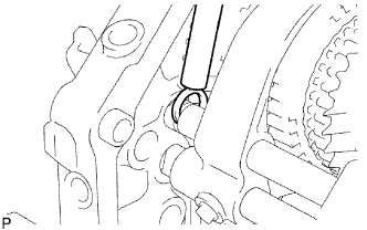
INSTALL NO. 1 GEAR SHIFT FORK SHAFT
-
Coat the No. 1 shift interlock pin with MP grease.
-
Using a magnet hand, install the No. 1 shift interlock pin to the intermediate plate.
-
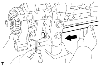
Pass the No. 1 gear shift fork shaft through the intermediate plate and No. 2 gear shift fork to install it.
-
Install the bolt to the No. 1 shift fork.
- Torque:
- 20 N*m { 204 kgf*cm, 15 ft.*lbf }
-
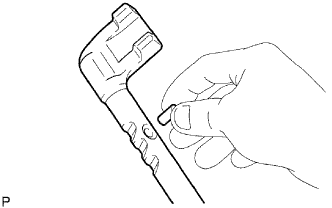
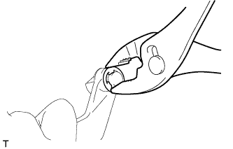
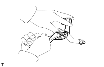
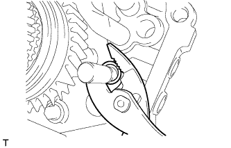
Using pliers, install the shaft snap ring to the No. 1 gear shift fork shaft.
-
-
INSTALL REVERSE SHIFT ARM
-
Install the shift arm shoe E-ring and the shift arm shoe to the reverse shift arm.
-
Install the reverse shift arm E-ring and reverse shift fork to the reverse shift arm.
-
Install the reverse shift arm to the reverse shift arm bracket.
-
-
INSTALL NO. 2 SHIFT INTERLOCK PIN
-
Coat the No. 2 shift interlock pin with MP grease, and install it to the No. 3 gear shift fork shaft.
-
-
INSTALL NO. 3 SHIFT INTERLOCK PIN
-
Coat the No. 3 shift interlock pin with MP grease.
-
Using a magnet hand, install the No. 3 shift interlock pin to the intermediate plate.
-
-
INSTALL NO. 3 GEAR SHIFT FORK SHAFT
-
Install the No. 3 gear shift fork shaft through the reverse shift fork and intermediate plate.
-
Install the reverse shift head ring to the reverse shift fork shaft.
-
Using a 5 mm pin punch and a hammer, tap in the slotted spring pin to the No. 3 shift fork shaft.
-
-
INSTALL NO. 5 GEAR SHIFT FORK SHAFT
-
Install the No. 5 gear shift fork shaft and reverse shift head.
-
Using a 5 mm pin punch and hammer, tap in the slotted spring pin to the No. 3 shift fork shaft.
-
-
INSTALL NO. 4 GEAR SHIFT FORK SHAFT
-
Coat the 2 shift detent balls with MP grease.
-
Using a magnet hand, install the 2 shift detent balls to the intermediate plate.
-
Pass the No. 4 gear shift fork shaft through the reverse shift fork, intermediate plate and reverse shift head to install it.
-
Install a new No. 3 gear shift fork with the bolt.
- Torque:
- 20 N*m { 204 kgf*cm, 15 ft.*lbf }
-
-
INSTALL NO. 2 SHIFT DETENT BALL
-
Coat the No. 2 detent ball with MP grease.
-
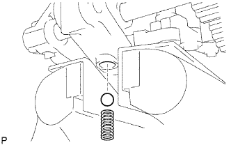
Install the No. 2 detent ball and compression spring to the intermediate plate.
-
Coat the spring seat with adhesive.
Adhesive Toyota Genuine Adhesive 1344, Three Bond 1344 or equivalent -
Using a T40 "TORX" socket, install the spring seat to the intermediate plate.
- Torque:
- 19 N*m { 194 kgf*cm, 14 ft.*lbf }
-
-
INSTALL SHIFT DETENT BALL
-
Coat the 3 shift detent balls with MP grease, and then install them and the 3 compression springs to the intermediate plate.
-
Coat the spring seat and 2 ball plugs with adhesive.
Adhesive Toyota Genuine Adhesive 1344, Three Bond 1344 or equivalent -
Using a T40 "TORX" socket, install the spring seat and 2 ball plugs to the intermediate plate.
- Torque:
- 19 N*m { 194 kgf*cm, 14 ft.*lbf }
-
-
INSTALL MANUAL TRANSMISSION CASE
-
Text in Illustration *1 Seal Packing Apply seal packing to the transmission case as shown in the illustration.
Seal packing Toyota Genuine Seal Packing 1281, Three Bond 1281 or equivalent -
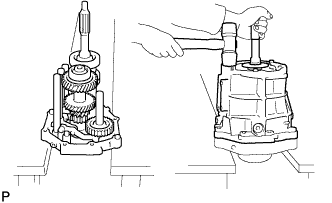
Stand the intermediate plate as shown in the illustration.
-
Using a plastic-faced hammer, install the transmission case to the intermediate plate as shown in the illustration.
-
-
INSTALL NO. 1 COUNTER GEAR FRONT BEARING SNAP RING
-
Using a snap ring expander, install the snap ring to the counter gear front bearing.
-
-
INSTALL FRONT BEARING SHAFT SNAP RING
-
Using a snap ring expander, install the snap ring to the input shaft front bearing.
-
-
INSTALL TRANSMISSION FRONT BEARING RETAINER OIL SEAL
-
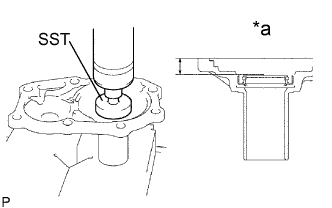
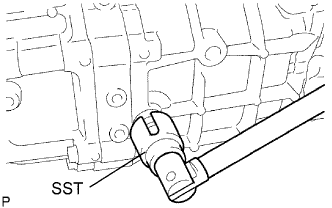
Text in Illustration *a Oil Seal Depth Using SST, press in a new oil seal to the front bearing retainer.
- SST
- 09950-60010 ( 09951-00440, 09952-06010 )
Standard depth 12.2 to 13.2 m (0.480 to 0.519 in.) Note
Do not damage the oil seal lip.
-
Apply a light coat of MP grease to the lip of the oil seal.
-
-
INSTALL FRONT BEARING RETAINER
-
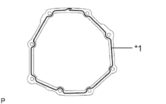
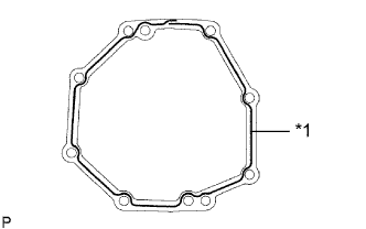
Install a new gasket and the front bearing retainer to the transmission case.
-
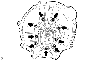
Install the 8 bolts.
- Torque:
- 17 N*m { 173 kgf*cm, 13 ft.*lbf }
-
-
INSTALL TRANSFER ADAPTER OIL SEAL
-
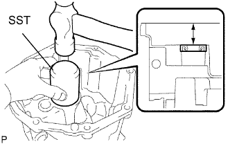
Using SST, tap in a new oil seal to the transfer adaptor.
- SST
- 09223-00010
Standard depth 45 to 46 mm (1.78 to 1.81 in.) Note
Be careful not to damage the lip of the oil seal.
-
Apply a light coat of MP grease to the lip of the oil seal.
-
-
INSTALL NO. 1 REVERSE RESTRICT PIN ASSEMBLY
-
Install the restrict pin to the transfer adaptor.
-
Using a 5 mm pin punch and hammer, tap in the slotted spring pin to the transfer adaptor.
-
Using a T40 "TORX" socket, install the plug to the transfer adaptor.
- Torque:
- 19 N*m { 194 kgf*cm, 14 ft.*lbf }
-
-
INSTALL SHIFT AND SELECT LEVER
-
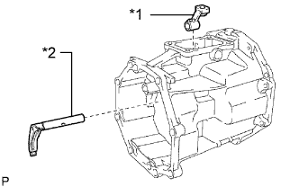
Text in Illustration *1 Shift Lever Housing *2 Shift and Select Lever Install the shift and select lever and shift lever housing to the transfer adaptor.
-
-
INSTALL TRANSFER OIL RECEIVER PIPE
-
Install the oil receiver pipe to the transfer adaptor.
-
-
INSTALL TRANSMISSION MAGNET
-
Install the magnet to the transfer adaptor.
-
-
INSTALL TRANSFER ADAPTER
-
Text in Illustration *1 Seal Packing Apply seal packing to the transfer adaptor as shown in the illustration.
Seal packing Toyota Genuine Seal Packing 1281, Three Bond 1281 or equivalent -
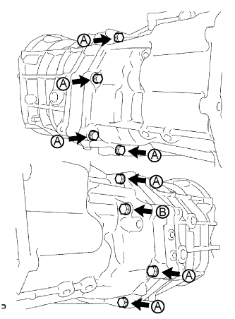
Install the transfer adaptor to the manual transmission case with the 8 bolts.
- Torque:
- 37 N*m { 377 kgf*cm, 27 ft.*lbf }
Tech Tips
Each bolt length is indicated below.
80 mm (3.15 in.) for bolt A
130 mm (5.12 in.) for bolt B
-
Install the bolt to the shift lever housing.
- Torque:
- 33 N*m { 340 kgf*cm, 25 ft.*lbf }
-
-
INSTALL SHIFT DETENT BALL
-
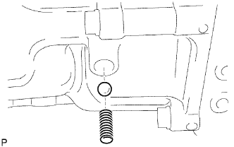
Coat the shift detent ball with MP grease, and then install it and the compression spring to the transfer adapter.
-
Using a T40 "TORX" socket, install the spring seat to the transfer adapter.
- Torque:
- 19 N*m { 194 kgf*cm, 14 ft.*lbf }
-
-
INSTALL FLOOR SHIFT CONTROL SHIFT LEVER RETAINER SUB-ASSEMBLY
-
Install a new gasket to the transfer adapter.
-
Install the shift lever retainer with the 4 bolts.
- Torque:
- 18 N*m { 184 kgf*cm, 13 ft.*lbf }
-
-
INSTALL RESTRICT PIN
-
Install the 2 restrict pins to the transfer adaptor.
- Torque:
- 28 N*m { 286 kgf*cm, 21 ft.*lbf }
-
-
INSTALL FRONT TRANSMISSION CASE
-
Install the front transmission case.
-
Apply adhesive to the bolt threads.
Adhesive Toyota Genuine Adhesive 1344, Three Bond 1344 or equivalent -
Install the 9 bolts.
- Torque:
- 37 N*m { 377 kgf*cm, 27 ft.*lbf }
-
-
INSTALL BACK-UP LIGHT SWITCH ASSEMBLY
-
Using SST, install a new gasket and the back-up light switch to the manual transmission case.
- SST
- 09817-16011
- Torque:
- 37 N*m { 377 kgf*cm, 27 ft.*lbf }
-
-
INSTALL CLUTCH RELEASE FORK BOOT
-
Install the release fork boot to the front transmission case.
-
-
INSTALL RELEASE FORK SUPPORT
-
Install the release fork support to the front transmission case.
- Torque:
- 39 N*m { 400 kgf*cm, 29 ft.*lbf }
-
-
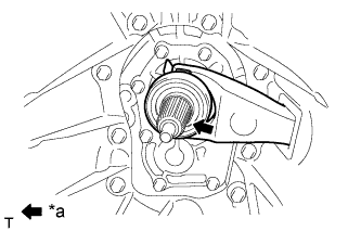
INSTALL CLUTCH RELEASE BEARING ASSEMBLY
Text in Illustration *a Release hub grease
-
Apply release hub grease to the clutch release bearing, and then install it to the clutch release fork with the clip.
Grease Toyota Genuine Release Hub Grease or equivalent
-
-
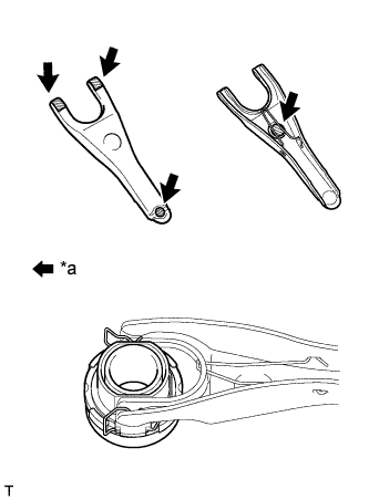
INSTALL CLUTCH RELEASE FORK SUB-ASSEMBLY
-
Install the clutch release fork.
Note
After the installation, move the fork forward and backward to check that the release bearing slides smoothly.
-
Text in Illustration *a Clutch spline grease Apply clutch spline grease to the spline of the input shaft.
Grease Toyota Genuine Clutch Spline Grease or equivalent
-
-
INSTALL DRAIN PLUG SUB-ASSEMBLY
-
Install a new gasket and the drain plug to the transmission case.
- Torque:
- 37 N*m { 377 kgf*cm, 27 ft.*lbf }
-
-
INSTALL MANUAL TRANSMISSION FILLER PLUG
-
Install a new gasket and the filler plug to the transmission case.
- Torque:
- 37 N*m { 377 kgf*cm, 27 ft.*lbf }
-