OUTPUT SHAFT REASSEMBLY

-
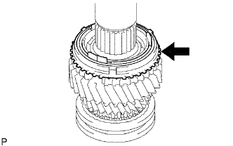
INSTALL NO. 2 TRANSMISSION HUB SLEEVE
-
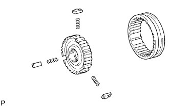
Install the 3 No. 2 synchromesh shifting key springs and 3 synchromesh shifting keys to the No. 2 clutch hub.
Note
Make sure that the No. 2 hub sleeve and No. 2 clutch hub are installed facing the proper directions.
-
Apply gear oil to the sliding part of the No. 2 hub sleeve, and install it to the No. 2 clutch hub.
-
-
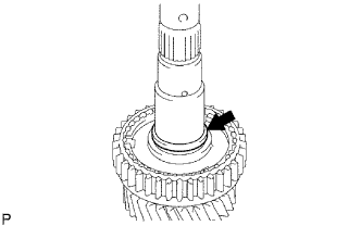
INSTALL 3RD GEAR NEEDLE ROLLER BEARING
-
Apply gear oil to the needle roller bearing and install it to the output shaft.
-
-
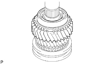
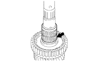
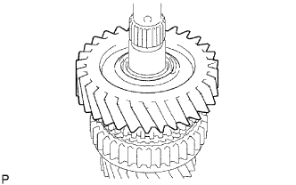
INSTALL 3RD GEAR
-
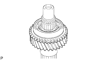
Apply gear oil to the 3rd gear and install it to the output shaft.
-
-
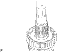
INSTALL NO. 2 SYNCHRONIZER RING (for 3rd Gear)
-
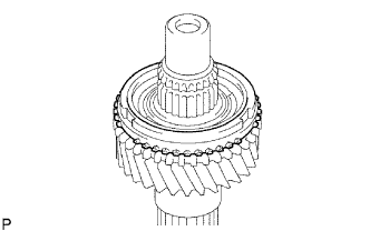
Apply gear oil to the No. 2 synchronizer ring and install it to the 3rd gear.
-
-
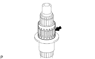
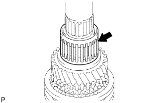
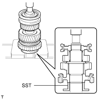
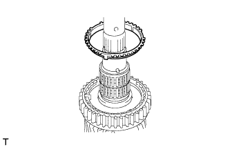
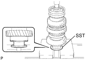
INSTALL NO. 2 TRANSMISSION CLUTCH HUB
-
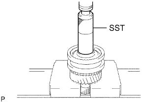
Using SST and a press, install the No. 2 clutch hub to the output shaft.
- SST
- 09608-06041
Note
-
Install the hub while aligning the positions of the shifting keys with the key grooves of the No. 2 synchronizer ring.
-
Make sure the 3rd gear rotates smoothly.
-
Select a snap ring that makes the clearance between the No. 2 clutch hub and snap ring within the specification.
Standard clearance 0.10 mm (0.00394 in.) or less Standard Snap Ring Mark Thickness A 1.80 to 1.85 mm (0.0709 to 0.0728 in.) B 1.85 to 1.90 mm (0.0728 to 0.0748 in.) C 1.90 to 1.95 mm (0.0748 to 0.0768 in.) D 1.95 to 2.00 mm (0.0768 to 0.0787 in.) E 2.00 to 2.05 mm (0.0787 to 0.0807 in.) F 2.05 to 2.10 mm (0.0807 to 0.0827 in.) G 2.10 to 2.15 mm (0.0827 to 0.0846 in.) -
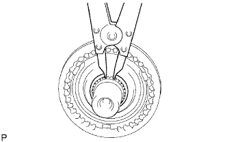
Using a snap ring expander, install the snap ring.
Note
Do not damage the sliding surface of the bearing.
-
-
INSTALL 2ND GEAR NEEDLE ROLLER BEARING
-
Apply gear oil to the needle roller bearing, and install it to the output shaft.
-
-
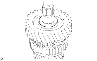
INSTALL 2ND GEAR
-
Apply gear oil to the 2nd gear and install it to the output shaft.
-
-
INSTALL NO. 1 SYNCHRONIZER RING SET (for 2nd Gear)
-
Apply gear oil to the No. 1 synchronizer ring set and install it to the 2nd gear.
-
-
INSTALL REVERSE GEAR
-
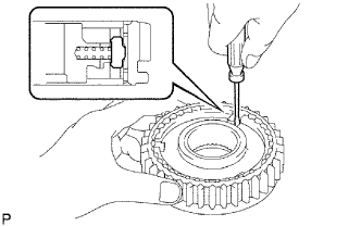
Using a screwdriver, install the 3 synchromesh shifting key springs and 3 No. 1 synchromesh shifting keys to the No. 1 clutch hub.
-
Apply gear oil to the reverse gear and install it to the No. 1 clutch hub.
-
-
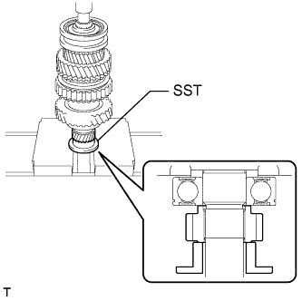
INSTALL NO. 1 TRANSMISSION CLUTCH HUB
-
Using SST and a press, install the No. 1 clutch hub to the output shaft.
- SST
- 09316-60011 ( 09316-00041 )
Note
-
Make sure that the No. 1 synchromesh shifting key positions are aligned with the No. 1 synchronizer ring key grooves.
-
Make sure the 1st gear rotates freely.
-
Select a snap ring that makes the thrust clearance between the No. 1 clutch hub and snap ring to be within the specification.
Standard clearance 0.1 mm (0.00394 in.) or less Note
Do not damage the journal surface of the snap ring.
Standard Snap Ring Mark Thickness A 2.30 to 2.35 mm (0.0906 to 0.0925 in.) B 2.35 to 2.40 mm (0.0925 to 0.0945 in.) C 2.40 to 2.45 mm (0.0945 to 0.0965 in.) D 2.45 to 2.50 mm (0.0965 to 0.0984 in.) E 2.50 to 2.55 mm (0.0984 to 0.1004 in.) F 2.55 to 2.60 mm (0.1004 to 0.1024 in.) G 2.60 to 2.65 mm (0.1024 to 0.1043 in.) -
Using a brass bar and hammer, tap on the snap ring.
-
-
INSTALL 1ST GEAR BEARING SPACER
-
Apply gear oil to the bearing spacer and install it to the output shaft.
-
-
INSTALL 1ST GEAR NEEDLE ROLLER BEARING
-
Apply gear oil to the needle roller bearing and install it to the output shaft.
-
-
INSTALL 1ST GEAR THRUST WASHER PIN
-
Install the thrust washer pin to the output shaft.
-
-
INSTALL NO. 1 SYNCHRONIZER RING SET (for 1st Gear)
-
Apply gear oil to the No. 1 synchronizer ring set and install it to the output shaft.
-
-
INSTALL 1ST GEAR
-
Apply gear oil to the 1st gear and install it to the output shaft.
-
-
INSTALL 1ST GEAR THRUST WASHER
-
Apply gear oil to the thrust washer and install it to the output shaft.
-
-
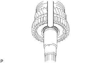
INSTALL OUTPUT SHAFT CENTER BEARING
-
Using SST and a press, install a new center bearing to the output shaft.
- SST
- 09316-60011 ( 09316-00031 )
Note
Install the center bearing so that the snap ring groove of the bearing faces the rear side.
-
-
INSTALL 5TH GEAR
-
Using SST and a press, install the 5th gear to the output shaft.
- SST
- 09316-60011 ( 09316-00031 )
Note
-
Check that the 5th gear and the splines of the output shaft fit before installing the 5th gear.
-
Make sure face the convex part of the gear faces the front side.
-
-
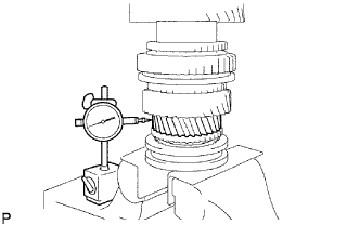
INSPECT 1ST GEAR THRUST CLEARANCE
-
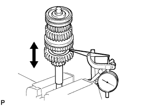
Using a dial indicator, measure the thrust clearance.
Standard clearance 0.20 to 0.45 mm (0.00787 to 0.0177 in.)
-
If the clearance is not as specified, replace the No. 1 synchronizer ring set.
-
-
-
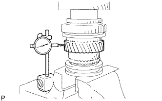
INSPECT 2ND GEAR THRUST CLEARANCE
-
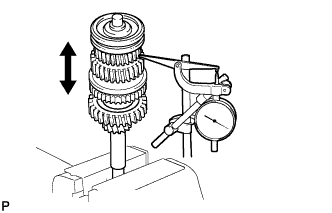
Using a dial indicator, measure the thrust clearance.
Standard clearance 0.10 to 0.25 mm (0.00394 to 0.00984 in.)
-
If the clearance is not as specified, replace the No. 1 synchronizer ring set.
-
-
-
INSPECT 3RD GEAR THRUST CLEARANCE
-
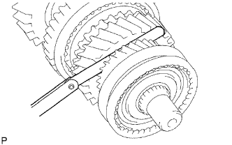
Using a feeler gauge, measure the thrust clearance.
Standard clearance 0.10 to 0.25 mm (0.00394 to 0.00984 in.)
-
If the clearance is not as specified, replace the No. 2 synchronizer ring set.
-
-
-
INSPECT 1ST GEAR RADIAL CLEARANCE
-
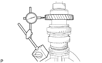
Using a dial indicator, measure the radial clearance.
Standard clearance 0.020 to 0.073 mm (0.000785 to 0.00287 in.)
-
If the clearance is not as specified, replace the 1st gear needle roller bearing with a new one.
-
-
-
INSPECT 2ND GEAR RADIAL CLEARANCE
-
Using a dial indicator, measure the radial clearance.
Standard clearance 0.015 to 0.068 mm (0.000591 to 0.00267 in.)
-
If the clearance is not as specified, replace the 2nd gear needle roller bearing with a new one.
-
-
-
INSPECT 3RD GEAR RADIAL CLEARANCE
-
Using a dial indicator, measure the radial clearance.
Standard clearance 0.015 to 0.068 mm (0.000591 to 0.00267 in.)
-
If the clearance is not as specified, replace the 3rd gear needle roller bearing with a new one.
-
-