OIL COOLER (for 1GR-FE) INSTALLATION

-
INSTALL OIL COOLER ASSEMBLY (w/ Air Cooled Transmission Oil Cooler)
-
Install the 2 oil cooler brackets with the 2 bolts.
- Torque:
- 5.5 N*m { 56 kgf*cm, 49 in.*lbf }
-
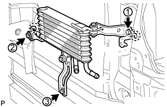
Attach the claws of the oil cooler to the hole of the radiator support and the center brace in that order to install it.
-
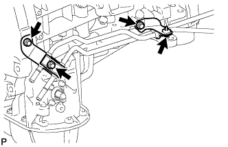
Install the 3 bolts and tighten the bolts in the order shown in the illustration.
- Torque:
- 5.5 N*m { 56 kgf*cm, 49 in.*lbf }
-
-
INSTALL NO. 3 OIL COOLER TUBE SUB-ASSEMBLY (w/ Air Cooled Transmission Oil Cooler)
-
Pass the No. 3 oil cooler tube through the hole of radiator support from the rear of the vehicle and install it to the oil cooler bracket with the bolt.
- Torque:
- 5.5 N*m { 56 kgf*cm, 49 in.*lbf }
-
-
INSTALL NO. 6 INLET OIL COOLER HOSE AND NO. 6 OUTLET OIL COOLER HOSE (w/ Air Cooled Transmission Oil Cooler)
-
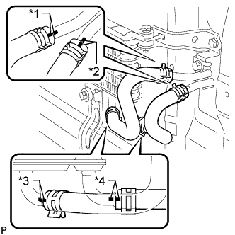
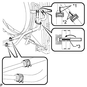
Text in Illustration *1 Blue Paint Mark *2 Pink Paint Mark *3 Yellow Paint Mark *4 White Paint Mark Connect the No. 6 oil cooler inlet hose and No. 6 oil cooler outlet hose to the oil cooler.
-
Connect the 2 hoses to the No. 3 oil cooler tube to install them.
Note
Make sure the pinching portion of each clip is facing the direction shown in the illustration and the paint marks are aligned as shown in the illustration.
-
-
INSTALL NO. 2 OIL COOLER TUBE SUB-ASSEMBLY
-
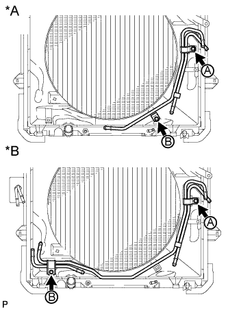
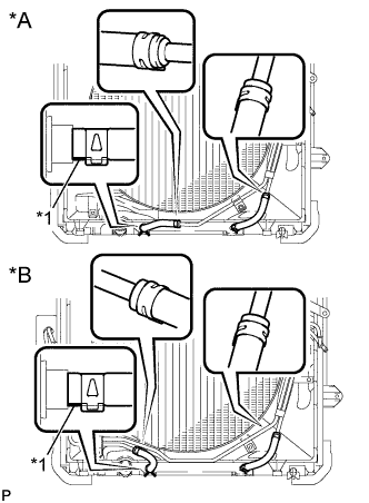
Text in Illustration *A w/o Air Cooled Transmission Oil Cooler *B w/ Air Cooled Transmission Oil Cooler Temporarily install the oil cooler tube to the fan shroud with bolt A. Install bolt B and tighten it to the specified torque. Then tighten bolt A to the specified torque.
- Torque:
- 5.5 N*m { 56 kgf*cm, 49 in.*lbf }
-
-
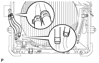
INSTALL NO. 5 OIL COOLER INLET HOSE AND NO. 5 OIL COOLER OUTLET HOSE (w/ Air Cooled Transmission Oil Cooler)
-
Connect the No. 5 oil cooler inlet hose and No. 5 oil cooler outlet hose to the No. 2 oil cooler tube.
-
Connect the 2 hoses to the No. 3 oil cooler tube to install them.
Note
Make sure the pinching portion of each clip is facing the direction shown in the illustration.
-
-
INSTALL NO. 4 OIL COOLER INLET HOSE AND NO. 4 OIL COOLER OUTLET HOSE
-
Text in Illustration *A w/o Air Cooled Transmission Oil Cooler *B w/ Air Cooled Transmission Oil Cooler *1 Yellow Paint Mark Connect the No. 4 oil cooler inlet hose and No. 4 oil cooler outlet hose to the No. 2 oil cooler tube.
-
Connect the 2 hoses to the radiator to install them.
Note
-
When connecting the hoses to the tube, support the tube by hand and be careful to prevent the tube from being deformed.
-
Make sure the paint mark and pinching portion of each clip are facing the directions shown in the illustration.
-
-
-
INSTALL NO. 1 OIL COOLER INLET TUBE AND NO. 1 OIL COOLER OUTLET TUBE (w/o Air Cooled Transmission Oil Cooler)
-
Install the 2 No. 2 flexible hose clamps with the 2 bolts.
- Torque:
- 14 N*m { 143 kgf*cm, 10 ft.*lbf }
-
Install the No. 1 oil cooler inlet tube and No. 1 oil cooler outlet tube and close the 2 No. 2 flexible hose clamps with the 2 bolts.
- Torque:
- 5.5 N*m { 56 kgf*cm, 49 in.*lbf }
-
-
INSTALL NO. 1 OIL COOLER INLET TUBE AND NO. 1 OIL COOLER OUTLET TUBE (w/ Air Cooled Transmission Oil Cooler)
-
Install the 2 No. 2 flexible hose clamps with the 2 bolts.
- Torque:
- 14 N*m { 143 kgf*cm, 10 ft.*lbf }
-
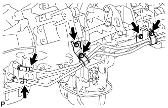
Temporarily install the ends of the 2 oil cooler tubes to each oil cooler tube union by hand.
-
Close the 2 No. 2 flexible hose clamps and install the 2 bolts.
- Torque:
- 5.5 N*m { 56 kgf*cm, 49 in.*lbf }
-
Using a union nut wrench, tighten the inlet and outlet tubes.
- Torque:
- 34 N*m { 347 kgf*cm, 25 ft.*lbf }
Note
Use the formula to calculate special torque values for situations where a union nut wrench is combined with a torque wrench Click here.
-
-
INSTALL NO. 3 OIL COOLER INLET HOSE AND NO. 3 OIL COOLER OUTLET HOSE
-
Text in Illustration *1 Blue Paint Mark *2 Pink Paint Mark *3 White Paint Mark Connect the No. 3 oil cooler inlet hose and No. 3 oil cooler outlet hose to the No. 1 oil cooler inlet tube and No. 1 oil cooler outlet tube.
-
Connect the 2 hoses to the No. 2 oil cooler tube to install them, and then pass the 2 hoses through the No. 1 flexible hose clamp and close the clamp.
Note
-
When connecting the hoses to the tube, support the tube by hand and be careful to prevent the tube from being deformed.
-
Make sure the paint marks and pinching portion of each clip are facing the directions shown in the illustration.
-
-
-
INSTALL TRANSMISSION OIL COOLER ASSEMBLY (w/o Air Cooled Transmission Oil Cooler)
-
Coat 2 new O-rings with ATF and install the O-rings to the groove of the transmission oil cooler.
-
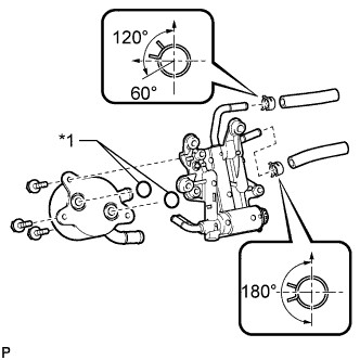
Text in Illustration *1 New O-Ring Align the transmission oil cooler with the transmission oil thermostat and assemble them with the 3 bolts.
- Torque:
- 14 N*m { 143 kgf*cm, 10 ft.*lbf }
-
Connect the No. 1 oil cooler inlet hose and No. 1 oil cooler outlet hose to the transmission oil thermostat.
Note
Make sure the pinching portion of each clip is facing the direction shown in the illustration.
-
Connect the 2 hoses to the oil cooler tube unions.
-
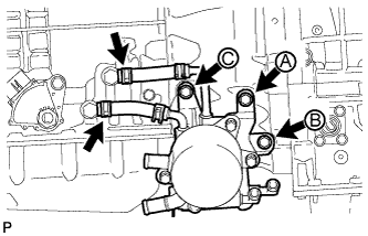
Temporarily install the transmission oil cooler together with the transmission oil thermostat with bolt A. Install bolts B and C and tighten them to the specified torque. Then tighten bolt A to the specified torque.
- Torque:
- 21 N*m { 214 kgf*cm, 15 ft.*lbf }
-
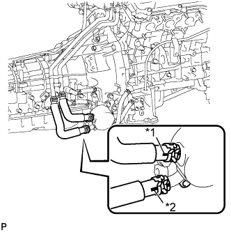
Text in Illustration *1 White Paint Mark *2 Yellow Paint Mark Connect the 2 water by-pass hoses to the transmission oil cooler.
Note
-
Make sure the pinching portion of each clip is facing the direction shown in the illustration.
-
Make sure the paint mark of each hose is facing outward.
-
-
-
INSTALL NO. 2 OIL COOLER INLET HOSE AND NO. 2 OIL COOLER OUTLET HOSE (w/o Air Cooled Transmission Oil Cooler)
-
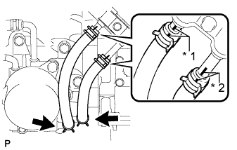
Text in Illustration *1 Blue Paint Mark *2 Pink Paint Mark Connect the No. 2 oil cooler inlet hose and No. 2 oil cooler outlet hose to the transmission oil thermostat.
-
Connect the 2 hoses to the No. 1 oil cooler inlet tube and No. 1 oil cooler outlet tube to install them.
Note
-
Make sure the pinching portion of each clip is facing the direction shown in the illustration.
-
Make sure the paint mark of each hose is facing outward.
-
-
-
ADD ENGINE COOLANT
-
Tighten the cylinder block drain cock plug.
- Torque:
- 13 N*m { 130 kgf*cm, 9 ft.*lbf }
-
Tighten the radiator drain cock plug by hand.
-
Add engine coolant.
Standard Capacity Item Specified Condition for Automatic Transmission w/o Warmer w/o Rear Heater 10.5 liters (11.1 US qts, 9.2 Imp. qts) w/ Rear Heater 12.3 liters (13.0 US qts, 10.8 Imp. qts) w/ Warmer w/o Rear Heater 11.0 liters (11.6 US qts, 9.7 Imp. qts) w/ Rear Heater 12.8 liters (13.5 US qts, 11.3 Imp. qts) for Manual Transmission w/o Rear Heater 10.7 liters (11.3 US qts, 9.4 Imp. qts) w/ Rear Heater 12.5 liters (13.2 US qts, 11.0 Imp. qts) Note
Do not substitute plain water for engine coolant.
Tech Tips
-
TOYOTA vehicles are filled with TOYOTA SLLC at the factory. In order to avoid damage to the engine cooling system and other technical problems, only use TOYOTA SLLC or similar high quality ethylene glycol based non-silicate, non-amine, non-nitrite, non-borate coolant with long-life hybrid organic acid technology (coolant with long-life hybrid organic acid technology consists of a combination of low phosphates and organic acids).
-
Press the No. 1 and No. 2 radiator hoses several times by hand, and then check the coolant level. If the coolant level is low, add coolant.
-
-
Slowly pour coolant into the radiator reservoir until it reaches the F line.
-
Install the reservoir cap.
-
Install the radiator cap.*1
-
Start the engine and stop it immediately.*2
-
Allow approximately 10 seconds to pass. Then remove the radiator cap and check the coolant level. If the coolant level has decreased, add coolant.*3
-
Repeat steps *1, *2 and *3 until the coolant level does not decrease.
Tech Tips
Be sure to perform this step while the engine is cold, as air in the No. 1 radiator hose will flow into the radiator if the engine is warmed up and the thermostat opens.
-
Install the radiator cap.*4
-
Set the air conditioning as follows.*5
Item Condition Fan speed Any setting except off Temperature Toward WARM Air conditioning switch Off -
Start the engine, warm it up until the thermostat opens, and then continue to run the engine for several minutes to circulate the coolant.*6
CAUTION:
-
Wear protective gloves. Hot areas on the parts may injure your hands.
-
Be careful of the fan.
-
Be careful as the engine, radiator and radiator hoses are hot and can cause burns.
Note
-
Immediately after starting the engine, if the radiator reservoir does not have any coolant, perform the following: 1) stop the engine, 2) wait until the coolant has cooled down, and 3) add coolant until the coolant is filled to the F line.
-
Do not start the engine when there is no coolant in the radiator reservoir.
-
Pay attention to the needle of the engine coolant temperature receiver gauge. Make sure that the needle does not show an abnormally high temperature.
-
If there is not enough coolant, the engine may burn out or overheat.
Tech Tips
-
Press the No. 1 and No. 2 radiator hoses several times by hand to bleed air while warming up the engine.
-
The thermostat opening timing can be confirmed by pressing the No. 2 radiator hose by hand and checking when the engine coolant starts to flow inside the hose.
-
-
Stop the engine, wait until the engine coolant cools down to ambient temperature. Then remove the radiator cap and check the coolant level.*7
CAUTION:
Do not remove the radiator cap while the engine and radiator are still hot. Pressurized, hot engine coolant and steam may be released and cause serious burns.
-
If the coolant level has decreased, add coolant and warm up the engine until the thermostat opens.*8
-
If the coolant level has not decreased, check that the coolant level in the radiator reservoir is at the F line.
If the coolant level is below the F line, repeat steps *4 through *8.
If the coolant level is above the F line, drain coolant until the coolant level reaches the F line.
-
-
ADJUST AUTOMATIC TRANSMISSION FLUID LEVEL
-
Adjust the automatic transmission fluid level Click here.
-
-
INSPECT FOR COOLANT LEAK
CAUTION:
To avoid being burned, do not remove the radiator reservoir cap while the engine and radiator are still hot. Thermal expansion may cause hot engine coolant and steam to blow out from the radiator.
-
Fill the radiator with engine coolant, and then attach a radiator cap tester.
-
Warm up the engine.
-
Using the radiator cap tester, increase the pressure inside the radiator to 123 kPa (1.3 kgf/cm2, 18 psi), and then check that the pressure does not drop.
If the pressure drops, check the hoses, radiator and water pump for leakage. If there are no signs or traces of external engine coolant leakage, check the heater core, cylinder block and head.
-
-
INSTALL FRONT BUMPER COVER (w/ Air Cooled Transmission Oil Cooler)
-
Install the front bumper cover Click here.
-
-
INSTALL FRONT NO. 1 FENDER APRON TO FRAME SEAL RH
-
Install the front No. 1 fender apron to frame seal with the 5 clips.
-
-
INSTALL FRONT FENDER APRON SEAL RH
-
Install the front fender apron seal with the 5 clips.
-
-
INSTALL NO. 1 ENGINE UNDER COVER SUB-ASSEMBLY
-
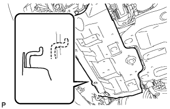
Hook the engine under cover to the vehicle body as shown in the illustration.
-
Install the 4 bolts.
- Torque:
- 29 N*m { 296 kgf*cm, 21 ft.*lbf }
-
-
INSTALL REAR ENGINE UNDER COVER ASSEMBLY
-
Install the rear engine under cover with the 4 bolts.
- Torque:
- 29 N*m { 296 kgf*cm, 21 ft.*lbf }
-