BACK DOOR REASSEMBLY

Tech Tips
A bolt without a torque specification is shown in the standard bolt chart Click here.
-
INSTALL LICENSE PLATE LIGHT ASSEMBLY
-
w/o Back Door Tire Carrier:
Install the license plate light assembly Click here.
-
w/ Back Door Tire Carrier:
Install the license plate light assembly Click here.
-
-
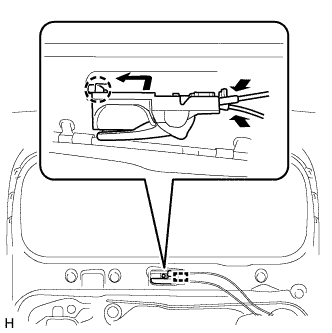
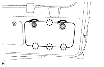
INSTALL BACK DOOR ELECTRICAL KEY SWITCH (w/ Back Door Tire Carrier)
-
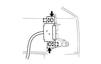
Attach the 2 guides to install the back door electrical key switch.
-
Install the 2 screws.
-
-
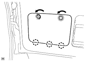
INSTALL BACK DOOR ELECTRICAL KEY SWITCH (w/o Back Door Tire Carrier)
-
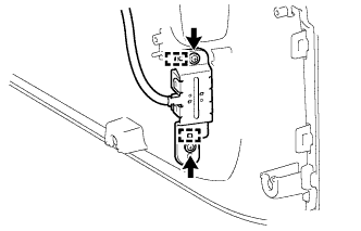
Attach the 2 guides to install the back door electrical key switch.
-
Install the 2 screws.
-
Attach the clamp.
-
-
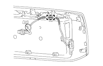
INSTALL REAR LICENSE LIGHT COVER
-
Install the rear license light cover with the 5 screws.
-
-
INSTALL NO. 1 BACK DOOR GARNISH RETAINER (w/o Back Door Tire Carrier)
-
Install the No. 1 back door garnish retainer with the 3 screws.
-
-
INSTALL LICENSE PLATE LIGHT CORD (w/o Entry and Start System)
-
w/o Back Door Tire Carrier:
Install the license plate light cord Click here.
-
w/ Back Door Tire Carrier:
Install the license plate light cord Click here.
-
-
INSTALL BACK DOOR OUTSIDE GARNISH SUB-ASSEMBLY
-
w/o Back Door Tire Carrier:
Install the back door outside garnish Click here.
-
w/ Back Door Tire Carrier:
Install the back door outside garnish Click here.
-
-
INSTALL BACK DOOR LOWER DAMPER STAY BRACKET LH
-
Bumper side:
-
Install a new back door check to the back door lower damper stay bracket.
-
-
Back door side:
-
Install the back door check to the back door lower damper stay bracket.
-
-
Check that the back door check is securely attached to the ball joint and cannot be pulled off.
-
-
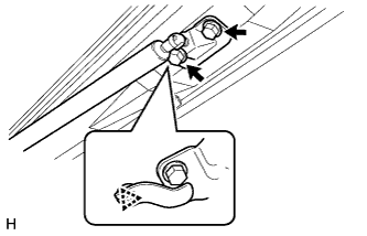
INSTALL BACK DOOR CHECK
-
Bumper side:
-
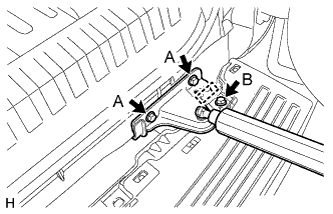
Install the back door check with back door lower damper stay bracket with the 2 bolts labeled A.
- Torque:
- 30 N*m { 306 kgf*cm, 22 ft.*lbf }
-
Install the bolt labeled B.
- Torque:
- 8.0 N*m { 82 kgf*cm, 71 in.*lbf }
-
Attach the wire harness.
-
-
Back door side:
-
Attach the clip to install the back door check with back door lower damper stay bracket.
-
Install the 2 bolts.
- Torque:
- 30 N*m { 306 kgf*cm, 22 ft.*lbf }
-
-
-
INSTALL BACK DOOR CUSHION (w/ Back Door Tire Carrier)
-
Install the 3 back door cushions.
-
-
INSTALL BACK DOOR GLASS (w/o Back Door Tire Carrier)
-
Install the back door glass with the 4 bolts.
- Torque:
- 20 N*m { 204 kgf*cm, 15 ft.*lbf }
-
Attach the 2 clamps and install the connector.
-
-
INSTALL BACK WINDOW STAY ASSEMBLY LH (w/o Back Door Tire Carrier)
-
Install the 2 stop rings to the back door stay assembly.
-
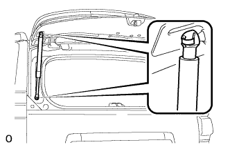
Install the back window stay assembly.
CAUTION:
Install the back window stay while supporting the back door glass by hand.
-
Check that the back window stay is attached to the ball joint and cannot be pulled off.
-
-
INSTALL BACK WINDOW STAY ASSEMBLY RH (w/o Back Door Tire Carrier)
Tech Tips
Use the same procedure described for the LH side.
-
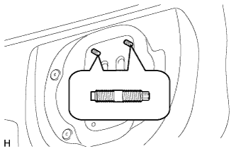
INSTALL BACK DOOR LOCK STRIKER COVER (w/o Back Door Tire Carrier)
-
When replacing the back door stay bolt with a new one:
-
Clean the threaded portion on the vehicle body with a non-residue solvent.
-
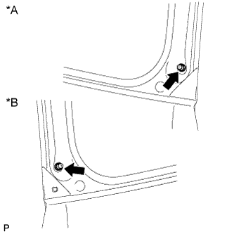
Text in Illustration *A for RH Side *B for LH Side Install the 2 back door stay bolts.
- Torque:
- 22 N*m { 224 kgf*cm, 16 ft.*lbf }
-
-
When reusing the back door stay bolt:
-
Clean the threaded portion on the vehicle body with a non-residue solvent.
-
Apply adhesive to the threads of the back door stay bolt.
Adhesive Toyota Genuine Adhesive 1324, Three Bond 1324 or equivalent -
Install the 2 back door stay bolts.
- Torque:
- 22 N*m { 224 kgf*cm, 16 ft.*lbf }
-
-
-
INSTALL NO. 1 BACK WINDOW WIPER MOTOR BRACKET (w/ Back Door Tire Carrier)
-
Attach the 2 clips to install the No. 1 back window wiper motor bracket.
-
Install the 3 bolts.
-
Attach the washer hose clamp.
-
-
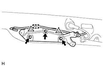
INSTALL REAR WIPER MOTOR ASSEMBLY
-
Attach the 2 guides and temporarily install the rear wiper motor assembly with the 3 bolts.
-
Tighten the 3 bolts.
- Torque:
- 5.5 N*m { 56 kgf*cm, 49 in.*lbf }
-
Connect the connector.
-
-
INSTALL REAR WIPER ARM
-
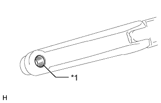
Text in Illustration *1 Wiper Arm Pivot Serrations Clean the wiper arm serrations.
-
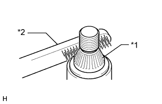
Text in Illustration *1 Wiper Pivot Serrations *2 Wire Brush Clean the wiper pivot serrations with a wire brush.
-
Operate the rear wiper and stop the rear wiper motor at the automatic stop position.
Tech Tips
The wiper motor does not operate if the back door and back door glass are not closed.
-
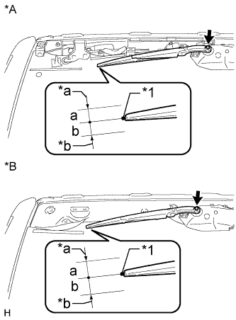
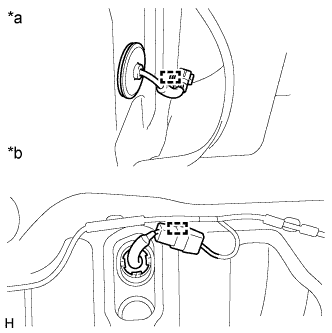
Text in Illustration *A w/o Back Door Tire Carrier *B w/ Back Door Tire Carrier *1 Ceramic Dot *a Upper Limit *b Lower Limit Align the blade tip with the mark on the glass as shown in the illustration.
Standard Area Standard Condition a 10.0 mm (0.394 in.) b 10.0 mm (0.394 in.) -
Install the rear wiper arm and blade assembly with the nut.
- Torque:
- 5.5 N*m { 56 kgf*cm, 49 in.*lbf }
Tech Tips
Hold the wiper arm by hand while tightening the nut.
-
-
INSTALL REAR WASHER NOZZLE SUB-ASSEMBLY
-
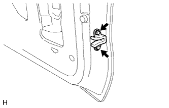
Attach the 2 claws to install the washer nozzle.
-
Connect the hose.
-
-
INSTALL NO. 2 BACK DOOR STIFFENER (w/ Back Door Tire Carrier)
Tech Tips
Use the same procedure to install the No. 2 back door stiffener on the other side.
-
Attach the 2 claws to install a new No. 2 back door stiffener.
-
-
INSTALL REAR SPOILER SUB-ASSEMBLY
-
w/o Back Door Tire Carrier:
Install the rear spoiler sub-assembly Click here.
-
w/ Back Door Tire Carrier:
Install the rear spoiler sub-assembly Click here.
-
-
INSTALL REAR SPOILER COVER RH
-
Attach the 2 clips to install the rear spoiler cover.
-
-
INSTALL REAR NO. 1 SPOILER COVER (w/o Back Door Tire Carrier)
-
Attach the 5 clips and fastening tape to install the rear No. 1 spoiler cover.
-
-
INSTALL BACK WINDOW LOCK ASSEMBLY (w/o Back Door Tire Carrier)
-
Install the back window lock assembly with the 3 bolts.
- Torque:
- 8.0 N*m { 82 kgf*cm, 71 in.*lbf }
-
Connect the connector.
-
-
INSTALL BACK DOOR PANEL CUSHION (w/o Back Door Tire Carrier)
-
Install the 4 back door panel cushions.
-
-
INSTALL BACK DOOR NO. 1 STOPPER
-
Attach the 2 claws to install a new back door No. 1 stopper.
-
-
INSTALL BACK DOOR NO. 2 STOPPER CUSHION
-
Attach the claw to install the back door No. 2 stopper cushion.
-
-
INSTALL BACK DOOR SIDE FEMALE STOPPER SUB-ASSEMBLY LH
-
Install the back door side female stopper sub-assembly with the 2 bolts .
- Torque:
- 7.0 N*m { 71 kgf*cm, 62 in.*lbf }
-
-
INSTALL NO. 2 BACK DOOR WEATHERSTRIP (w/o Back Door Tire Carrier)
-
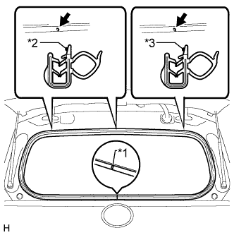
Text in Illustration *1 Joint of Weatherstrip *2 Paint Mark (White) *3 Paint Mark (Light Blue) Align the alignment mark on the weatherstrip with the protruding portion on the body indicated by the arrow in the illustration and install the No. 2 back door weatherstrip.
Note
After installation, check that the corners fit correctly.
-
-
INSTALL SWITCH COVER (w/o Back Door Tire Carrier)
-
Install the switch cover.
-
-
INSTALL GLASS HATCH OPENER SWITCH ASSEMBLY (w/o Back Door Tire Carrier)
-
Install the opener switch with the screw.
-
-
INSTALL LOWER BACK DOOR GARNISH SUB-ASSEMBLY OUTSIDE LH (w/o Back Door Tire Carrier)
-
Clean the vehicle body surface.
-
Using a heat light, heat the vehicle body surface.
-
Wipe off any tape with cleaner.
-
-
Install a new outside garnish.
-
Using a heat light, heat the vehicle body and garnish.
-
Remove the peeling paper from the face of the outside garnish.
-
-
Attach the 5 claws to install the garnish.
-
Install the screw.
-
Attach the clamp and connect the connector.
-
-
INSTALL LOWER BACK DOOR GARNISH SUB-ASSEMBLY OUTSIDE RH (w/o Back Door Tire Carrier)
-
Clean the vehicle body surface.
-
Using a heat light, heat the vehicle body surface.
Heating Temperature Item Temperature Vehicle body 40 to 60°C (104 to 140°F) Note
Do not heat the vehicle body excessively.
-
Wipe off any tape adhesive residue with cleaner.
-
-
Install a new rear lower back door garnish sub-assembly outside RH.
-
Using a heat light, heat the vehicle body and a new rear lower back door garnish sub-assembly outside RH.
-
Remove the release paper from the face of the rear lower back door garnish sub-assembly outside RH.
Tech Tips
After removing the release paper, keep the exposed adhesive free from foreign matter.
-
-
Attach the 4 claws to install the rear lower back door garnish sub-assembly outside RH, and then install the screw.
-
-
INSTALL LOWER BACK DOOR OUTSIDE GARNISH MOULDING LH (w/o Back Door Tire Carrier)
-
Attach the 4 claws to install the outside garnish moulding.
-
-
INSTALL LOWER BACK DOOR OUTSIDE GARNISH MOULDING RH (w/o Back Door Tire Carrier)
-
Attach the 5 claws to install the lower back door outside garnish moulding RH.
-
-
INSTALL NO. 2 BACK DOOR GARNISH RETAINER (w/o Back Door Tire Carrier, w/o Rear View Monitor System)
-
Install the No. 2 back door garnish retainer to the door panel with the 2 screws.
-
-
INSTALL REAR TELEVISION CAMERA ASSEMBLY (w/o Back Door Tire Carrier, w/ Rear View Monitor System)
-
Install the rear television camera with the 2 bolts.
-
Connect the connector.
-
-
INSTALL REAR NO. 1 WINDOW WIRE (w/ Back Door Tire Carrier, w/ Rear View Monitor System)
-
Text in Illustration *a Outer Side *b Inner Side Attach the 2 clamps to install the rear No. 1 window wire.
-
Connect the connector.
-
-
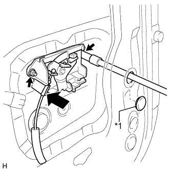
INSTALL BACK DOOR LOCK CONTROL CABLE ASSEMBLY
-
Install the cable.
-
-
INSTALL BACK DOOR LOCK ASSEMBLY
Note
-
When reusing the removed back door lock assembly, replace the door lock wiring harness seal on the connector with a new one.
-
Do not allow grease or dust to adhere to the surface of the connector which contacts the door lock wiring harness seal.
-
Reusing the door lock wiring harness seal or using a damaged door lock wiring harness seal may allow water into the connection. This may result in a malfunction of the front door lock assembly.
-
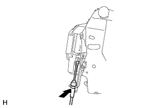
Connect the cable.
-
Install a new door lock wiring harness seal to the front door lock assembly.
-
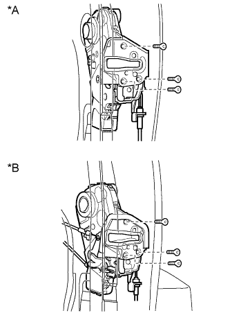
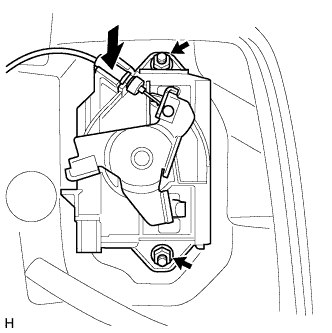
Text in Illustration *A for Standard Type *B w/ Back Door Tire Carrier, for Face to Face Seat Type Using a T30 "TORX" wrench, install the back door lock assembly with the 3 screws.
- Torque:
- 5.0 N*m { 51 kgf*cm, 44 in.*lbf }
-
Connect the connector.
-
-
INSTALL BACK DOOR OUTSIDE HANDLE LH
-
w/ Back Door Tire Carrier:
-
Text in Illustration *1 Hole Plug Connect the cable.
-
Install the back door outside handle with the 2 nuts.
- Torque:
- 5.0 N*m { 51 kgf*cm, 44 in.*lbf }
-
Install the hole plug.
-
-
w/o Back Door Tire Carrier:
-
Connect the cable.
-
Install the back door outside handle with the 2 nuts.
- Torque:
- 5.0 N*m { 51 kgf*cm, 44 in.*lbf }
-
-
-
INSTALL BACK DOOR SERVICE HOLE COVER
-
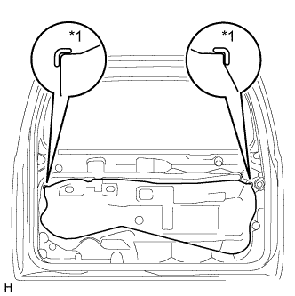
Text in Illustration *1 Reference Point Apply new butyl tape to the back door panel.
-
Attach the rear door service hole cover using to the reference points on the rear door panel.
Note
-
There should be no wrinkles or folds after attaching the service hole cover.
-
After attaching the service hole cover, check the seal quality.
-
-
-
INSTALL TOOL BOX BRACKET
-
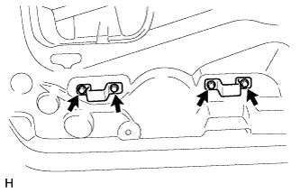
Install the 2 tool box brackets with the 4 bolts.
-
-
INSTALL BACK DOOR INSIDE HANDLE SUB-ASSEMBLY (for Face to Face Seat Type)
-
Connect the 2 cables to the inside handle sub-assembly.
-
Attach the claws and guide to install the inside handle sub-assembly.
-
-
INSTALL BACK DOOR TRIM PANEL ASSEMBLY
-
w/o Back Door Tire Carrier:
-
Attach the 15 clips to install the back door trim panel assembly.
-
Install the bolt.
-
-
w/ Back Door Tire Carrier:
-
Attach the 16 clips to install the back door trim panel assembly.
-
Install the bolt.
-
-
for Face to Face Seat Type:
-
Attach the 15 clips to install the back door trim panel assembly.
-
Install the bolt.
-
-
Install the screw.
-
Attach the claw to install the cover.
-
-
INSTALL BACK DOOR INSIDE HANDLE BEZEL (for Face to Face Seat Type)
-
Attach the 5 claws to install the back door inside handle bezel.
-
Install the screw.
-
-
INSTALL BACK DOOR LOCK COVER (w/o Back Door Tire Carrier)
-
Attach the 6 claws to install the back door lock cover.
-
-
INSTALL TOOL CASE
-
Attach the 2 claws to install the tool case.
-
-
INSTALL UPPER TOOL BOX PANEL SUB-ASSEMBLY
-
Attach the 3 claws.
-
Install the upper tool box panel sub-assembly as shown in the illustration.
-
-
INSTALL BACK DOOR TRIM COVER
-
Attach the 4 claws.
-
Install the back door trim cover as shown in the illustration.
-
-
INSTALL BACK DOOR SIDE GARNISH LH
-
Attach the 2 clips and claw to install the back door side garnish.
-
-
INSTALL BACK DOOR SIDE GARNISH RH
-
Attach the 2 clips and claw to install the back door side garnish.
-
-
INSTALL BACK DOOR CENTER GARNISH
-
Attach the 4 clips to install the back door center garnish.
-
-
INSTALL SPARE WHEEL CARRIER BRACKET SUB-ASSEMBLY (w/ Back Door Tire Carrier)
-
Using an E10 "TORX" socket wrench, install the 2 stud bolts.
- Torque:
- 42 N*m { 428 kgf*cm, 31 ft.*lbf }
-
Install the spare wheel carrier bracket sub-assembly with the 2 bolts and 2 nuts.
- Torque:
- 48 N*m { 489 kgf*cm, 35 ft.*lbf, for bolt and nut }
-
-
INSTALL REAR TELEVISION CAMERA ASSEMBLY (w/ Back Door Tire Carrier, w/ Rear View Monitor System)
-
Install the rear television camera with the bolt.
- Torque:
- 32 N*m { 326 kgf*cm, 24 ft.*lbf }
-
Connect the connector to install the rear No. 2 window wire.
-
-
INSTALL TELEVISION CAMERA BRACKET (w/ Back Door Tire Carrier, w/o Rear View Monitor System)
-
Install the rear television camera with the bolt.
- Torque:
- 32 N*m { 326 kgf*cm, 24 ft.*lbf }
-
Connect the connector to install the rear No. 2 window wire.
-
-
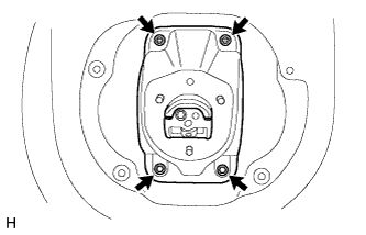
INSTALL NO. 2 SPARE WHEEL COVER (w/ Back Door Tire Carrier)
-
Install the No. 2 spare wheel cover with the 4 screws.
-
-
INSTALL SPARE TIRE (w/ Back Door Tire Carrier)
-
INSTALL SPARE WHEEL COVER (w/ Back Door Tire Carrier)
-
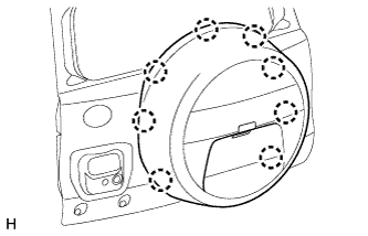
Attach the 8 claws to install the spare wheel cover.
-
Move the lever.
-
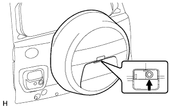
Install the bolt.
- Torque:
- 14 N*m { 143 kgf*cm, 10 ft.*lbf }
-
-
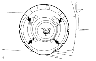
INSTALL SPARE WHEEL COVER PAD (w/ Back Door Tire Carrier)
-
Attach the 7 claws to install the wheel cover pad.
-