BACK DOOR ADJUSTMENT

Tech Tips
-
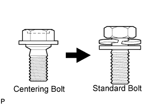
Centering bolts are used to mount the door hinge to the vehicle body and door. The door cannot be adjusted with the centering bolts installed. Substitute the centering bolts with standard bolts (with washers) when making adjustments.
-
The specified torque for standard bolts is shown in the standard bolt chart Click here.
-
INSPECT BACK DOOR
-
w/ Back Door Tire Carrier:
-
Check that the clearance measurements of areas A through I are within the standard range.
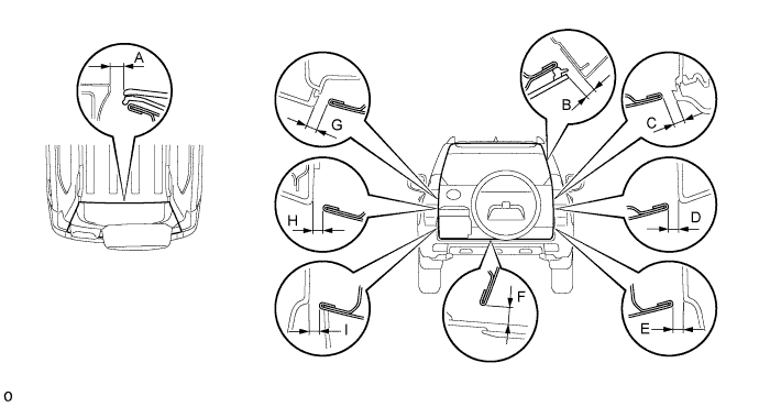
Standard Area Measurement Area Measurement A 8.35 to 11.35 mm (0.329 to 0.447 in.) B 4.65 to 7.65 mm (0.183 to 0.301 in.) C 5.05 to 8.05 mm (0.199 to 0.317 in.) D 5.25 to 8.25 mm (0.207 to 0.325 in.) E 5.25 to 8.25 mm (0.207 to 0.325 in.) F 8.85 to 11.85 mm (0.348 to 0.467 in.) G 4.85 to 7.85 mm (0.191 to 0.309 in.) H 5.25 to 8.25 mm (0.207 to 0.325 in.) I 5.25 to 8.25 mm (0.207 to 0.325 in.) - -
-
-
w/o Back Door Tire Carrier:
-
Check that the clearance measurements of areas A through I are within the standard range.
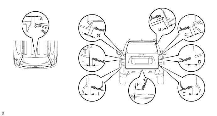
Standard Area Measurement Area Measurement A 8.35 to 11.35 mm (0.329 to 0.447 in.) B 5.05 to 8.05 mm (0.199 to 0.317 in.) C 4.65 to 7.65 mm (0.183 to 0.301 in.) D 4.95 to 7.95 mm (0.195 to 0.313 in.) E 4.95 to 7.95 mm (0.195 to 0.313 in.) F 8.85 to 11.85 mm (0.348 to 0.467 in.) G 4.65 to 7.65 mm (0.183 to 0.301 in.) H 4.95 to 7.95 mm (0.195 to 0.313 in.) I 5.05 to 8.05 mm (0.199 to 0.317 in.) - -
-
-
-
ADJUST BACK DOOR
-
w/ Back Door Tire Carrier:
-
Remove the spare wheel cover pad Click here.
-
Remove the spare wheel cover Click here.
-
Remove the spare tire.
-
-
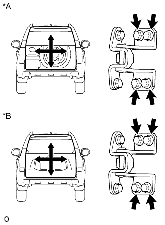
Text in Illustration *A w/ Back Door Tire Carrier *B w/o Back Door Tire Carrier Loosen the hinge bolts on the body and adjust the position of the door.
-
Tighten the hinge bolts on the body.
- Torque:
- 26 N*m { 265 kgf*cm, 19 ft.*lbf }
-
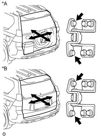
Text in Illustration *A w/ Back Door Tire Carrier *B w/o Back Door Tire Carrier Loosen the hinge bolts on the door and adjust the position of the door.
-
Tighten the hinge bolts on the door.
- Torque:
- 36 N*m { 367 kgf*cm, 27 ft.*lbf }
-
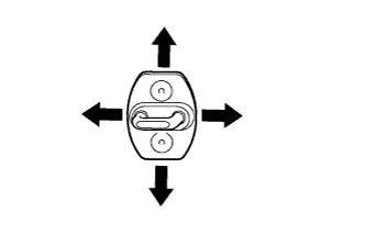
Using a T40 "TORX" socket, adjust the striker position by slightly loosening the striker mounting screws and then hitting the striker with a plastic-faced hammer.
-
Using a T40 "TORX" socket, tighten the striker mounting screws.
- Torque:
- 23 N*m { 235 kgf*cm, 17 ft.*lbf }
-
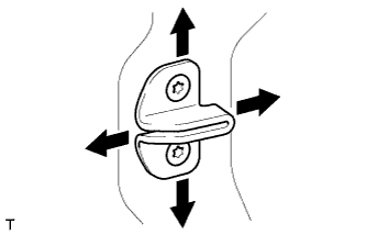
Using a T30 "TORX" socket, adjust the back door side male stopper position by slightly loosening the stopper mounting screws and then hitting the stopper with a plastic-faced hammer.
-
Using a T30 "TORX" socket, tighten the male stopper mounting screws.
- Torque:
- 7.0 N*m { 71 kgf*cm, 62 in.*lbf }
-
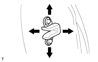
Loosen the back door side female stopper bolts and adjust the stopper position.
-
Tighten the female stopper bolts.
- Torque:
- 7.0 N*m { 71 kgf*cm, 62 in.*lbf }
-
w/ Back Door Tire Carrier:
-
Install the spare tire.
-
Install the spare wheel cover Click here.
-
Install the spare wheel cover pad Click here.
-
-