COMPRESSOR (for 2TR-FE) REMOVAL

-
REMOVE UPPER RADIATOR SUPPORT SEAL
-
Remove the 13 clips and upper radiator support seal.
-
-
RECOVER REFRIGERANT FROM REFRIGERATION SYSTEM
-
Start the engine.
-
Operate the cooler compressor under the conditions shown below:
Item Condition Engine Speed Idling Operating Time 3 minutes or more A/C Switch Status On Blower Switch Status HI Set Temperature MAX COOL This causes most of the compressor oil from the various components of the A/C system to collect in the A/C compressor.
Note
It is not necessary to operate the cooler compressor if the A/C does not operate because of compressor lock, etc.
-
Stop the engine.
-
Recover the refrigerant from the A/C system using a refrigerant recovery unit.
Tech Tips
Use the refrigerant recovery unit in accordance with the manufacturer's instruction manual.
-
-
REMOVE FRONT BUMPER COVER LOWER
-
Remove the clip, 5 bolts and front bumper cover lower.
-
-
REMOVE NO. 1 ENGINE UNDER COVER SUB-ASSEMBLY
-
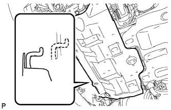
Remove the 4 bolts.
-
Unhook the engine under cover from the vehicle body as shown in the illustration.
-
-
DRAIN ENGINE COOLANT
CAUTION:
Do not remove the radiator cap while the engine and radiator are still hot. Pressurized, hot engine coolant and steam may be released and cause serious burns.
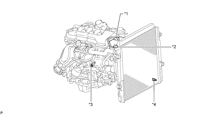
Text in Illustration *1 Reservoir Cap *2 Radiator Cap *3 Cylinder Block Drain Cock Plug *4 Radiator Drain Cock Plug
-
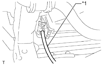
Text in Illustration *1 Vinyl Hose Install a vinyl hose to the radiator side.
-
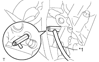
Text in Illustration *1 Vinyl Hose Install a vinyl hose to the engine side.
-
Loosen the radiator drain cock plug.
-
Remove the radiator cap and drain the coolant.
Tech Tips
Collect the coolant in a container and dispose of it according to the regulations in your area.
-
Loosen the cylinder block drain cock plug and drain the coolant from the engine.
-
-
REMOVE RADIATOR RESERVOIR
-
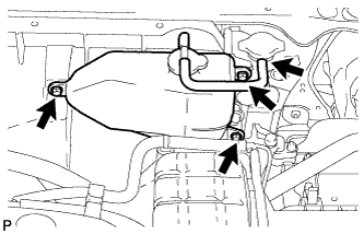
Disconnect the reservoir hose from the radiator.
-
Remove the 3 bolts and radiator reservoir.
-
-
REMOVE NO. 1 RADIATOR HOSE
-
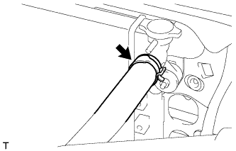
Disconnect the No. 1 radiator hose from the radiator.
-
-
REMOVE NO. 2 RADIATOR HOSE
-
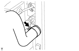
Disconnect the No. 2 radiator hose from the radiator.
-
-
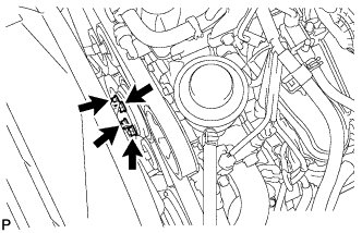
REMOVE FAN AND GENERATOR V BELT
-
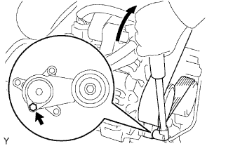
Use the hexagonal part indicated by the arrow in the illustration to move the tensioner pulley downward and decrease the tension in the V belt. Then remove the V belt.
Note
When removing the V belt, do not use the bolt of the idle pulley.
Tech Tips
After removing the drive belt, move the tensioner upward to the maximum amount.
-
-
REMOVE FAN SHROUD
-
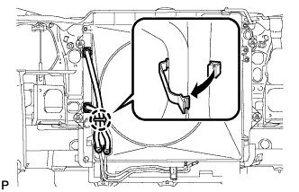
Detach the claw to open the flexible hose clamp.
-
Loosen the 4 nuts holding the fluid coupling fan.
-
Remove the fan and generator V-belt Click here.
-
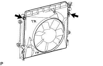
Remove the 2 bolts holding the fan shroud.
-
Remove the 4 nuts of the fluid coupling fan, and then remove the shroud together with the coupling fan.
Note
Be careful not to damage the radiator core.
-
-
DISCONNECT VANE PUMP ASSEMBLY
-
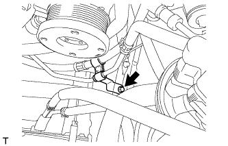
Remove the bolt and disconnect the pressure feed tube.
-
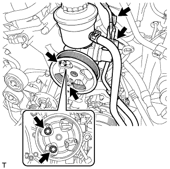
Disconnect the 2 connectors.
-
Remove the 2 bolts and disconnect the vane pump.
Tech Tips
It is not necessary to completely remove the vane pump. With the hoses connected to the vane pump, hang the vane pump on the vehicle body with a rope.
-
-
DISCONNECT DISCHARGE HOSE SUB-ASSEMBLY
-
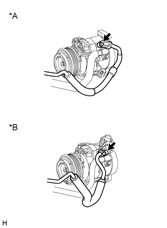
Text in Illustration *A except Model Code TRJ150L-GKMEKV, TRJ150L-GKPEKV, TRJ155L-GJPEKV *B Model Code TRJ150L-GKMEKV, TRJ150L-GKPEKV, TRJ155L-GJPEKV Remove the bolt and disconnect the discharge hose sub-assembly from the compressor.
-
Remove the O-ring from the discharge hose.
Note
Seal the openings of the disconnected parts using vinyl tape to prevent moisture and foreign matter from entering.
-
-
DISCONNECT SUCTION HOSE SUB-ASSEMBLY
-
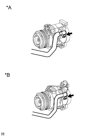
Text in Illustration *A except Model Code TRJ150L-GKMEKV, TRJ150L-GKPEKV, TRJ155L-GJPEKV *B Model Code TRJ150L-GKMEKV, TRJ150L-GKPEKV, TRJ155L-GJPEKV Remove the bolt and disconnect the suction hose sub-assembly from the compressor.
-
Remove the O-ring from the suction hose.
Note
Seal the openings of the disconnected parts using vinyl tape to prevent moisture and foreign matter from entering.
-
-
REMOVE COOLER COMPRESSOR ASSEMBLY
-
Disconnect the connector.
-
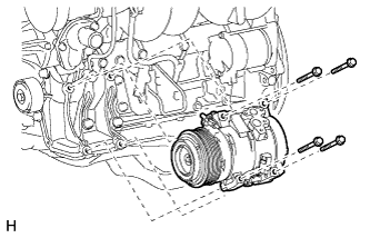
Remove the 4 bolts and compressor.
-