COMPRESSOR (for 5L-E) INSTALLATION

-
ADJUST COMPRESSOR OIL
-
When replacing the compressor with a new one, gradually release the refrigerant gas from the service valve and drain the following amount of oil from the new compressor before installation.
Standard (Oil capacity inside the new compressor: 80 + 15 cc (2.7 + 0.5 fl. oz.)) - (Remaining oil amount in the removed compressor) = (Oil amount to be removed from the new compressor) Note
-
When checking the compressor oil level, follow the A/C system precautions.
-
Since compressor oil remains in the pipes of the vehicle, if a new compressor is installed without removing some oil from the compressor, the oil amount becomes excessive. Excessive oil prevents heat exchange in the refrigerant cycle and causes refrigeration system failure.
-
If the volume of oil remaining in the removed compressor is too small, check for oil leakage.
-
Be sure to use ND-OIL 8 for compressor oil.
-
-
-
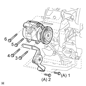
INSTALL COOLER COMPRESSOR ASSEMBLY
-
Temporarily install the cooler compressor with the 2 bolts.
-
Temporarily install the idle pulley with the 4 bolts.
-
Tighten the 6 bolts in the sequence shown in the illustration.
- Torque:
- for bolt A
- 45 N*m { 459 kgf*cm, 33 ft.*lbf }
- except bolt A
- 25 N*m { 255 kgf*cm, 18 ft.*lbf }
-
Connect the connector.
-
-
CONNECT NO. 1 COOLER REFRIGERANT SUCTION HOSE
-
Remove the vinyl tape attached to the hose.
-
Sufficiently apply compressor oil to a new O-ring and the fitting surface of the compressor.
Compressor oil ND-OIL 8 or equivalent -
Install the O-ring to the suction hose.
-
Connect the suction hose to the compressor with the bolt.
- Torque:
- 9.8 N*m { 100 kgf*cm, 87 in.*lbf }
-
-
CONNECT NO. 1 COOLER REFRIGERANT DISCHARGE HOSE
-
Remove the vinyl tape attached to the hose.
-
Sufficiently apply compressor oil to a new O-ring and the fitting surface of the compressor.
Compressor oil ND-OIL 8 or equivalent -
Install the O-ring to the discharge hose.
-
Connect the discharge hose to the compressor with the bolt.
- Torque:
- 9.8 N*m { 100 kgf*cm, 87 in.*lbf }
-
-
INSTALL COOLER COMPRESSOR V BELT
-
Install the V belt.
-
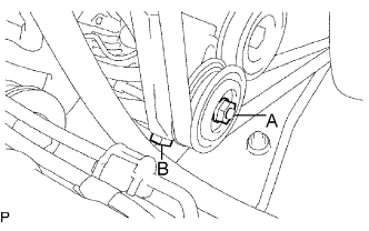
While tightening bolt B, adjust the tension of the V belt.
-
Tighten nut A.
- Torque:
- 39 N*m { 400 kgf*cm, 29 ft.*lbf }
-
Check the tension of the V belt Click here.
-
-
INSTALL AIR CLEANER CASE SUB-ASSEMBLY
-
Install the air cleaner case with the 3 bolts.
- Torque:
- 12 N*m { 122 kgf*cm, 9 ft.*lbf }
-
-
INSTALL AIR CLEANER FILTER ELEMENT SUB-ASSEMBLY
-
INSTALL AIR CLEANER CAP SUB-ASSEMBLY
-
Insert the hinge part of the air cleaner cap and hose into the air cleaner case, and then attach the 4 hook clamps.
-
Connect the air cleaner cap sub-assembly with the clamp.
- Torque:
- 5.0 N*m { 51 kgf*cm, 44 in.*lbf }
-
Attach the wire harness clamp.
-
Connect the 2 clamps and connector.
-
-
CHARGE REFRIGERANT
- SST
- 09985-20010 ( 09985-02130, 09985-02150, 09985-02090, 09985-02110, 09985-02010, 09985-02050, 09985-02060, 09985-02070 )
-
Perform vacuum purging using a vacuum pump.
-
Charge refrigerant HFC-134a (R134a).
Standard Model Code Air Conditioning Type Cool Box Refrigerant Charging Amount Except the model codes below w/o Rear Cooler w/ Cool Box 600 +/-30 g (21.2 +/-1.1 oz.) w/o Cool Box 550 +/-30 g (19.3 +/-1.1 oz.) w/ Rear Cooler w/ Cool Box 800 +/-30 g (28.2 +/-1.1 oz.) w/o Cool Box 770 +/-30 g (27.2 +/-1.1 oz.) w/ Rear Cooler
for Cold Area Specification Vehicles
w/o Cool Box 720 +/-30 g (25.3 +/-1.1 oz.) TRJ150L-GKMEKV
TRJ150L-GKPEKV
TRJ155L-GJPEKV
GRJ150L-GKFEKV
GRJ150L-GKAEKV
KDJ150L-GKFEYV
KDJ150L-GKAEYV
w/o Rear Cooler w/ Cool Box 600 +/-30 g (21.2 +/-1.1 oz.) w/o Cool Box 550 +/-30 g (19.3 +/-1.1 oz.) or 600 +/-30 g (21.2 +/-1.1 oz.) *1 w/ Rear Cooler w/ Cool Box 800 +/-30 g (28.2 +/-1.1 oz.) w/o Cool Box 770 +/-30 g (27.2 +/-1.1 oz.) *1: For vehicles with the 2TR-FE engine which have neither the rear cooler nor cool box, the refrigerant charging amount changes based on region.
Note
-
Do not operate the cooler compressor before charging refrigerant as the cooler compressor will not work properly without any refrigerant, and will overheat.
-
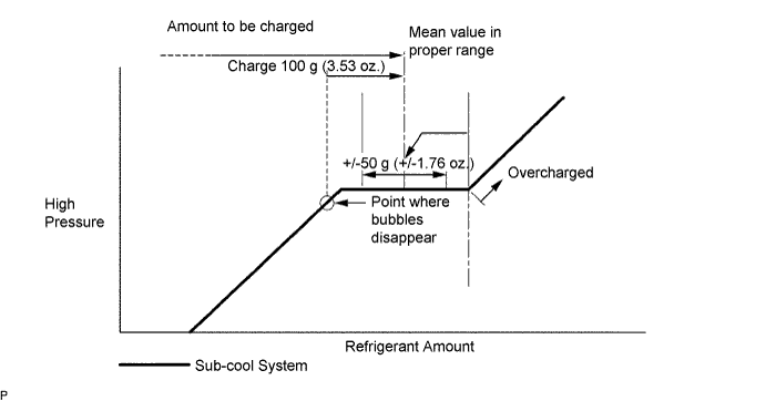
Approximately 100 g (3.53 oz.) of refrigerant may need to be charged after bubbles disappear. The refrigerant amount should be checked by measuring its quantity, and not with the sight glass.
-
-
INSTALL UPPER RADIATOR SUPPORT SEAL
-
Install the upper radiator support seal with the 13 clips.
-
-
WARM UP ENGINE
-
Warm up the engine at less than 1850 rpm for 2 minutes or more after charging the refrigerant.
Note
Be sure to warm up the compressor when turning the A/C switch is on after removing and installing the cooler refrigerant lines (including the compressor), to prevent damage to the compressor.
-
-
CHECK FOR REFRIGERANT GAS LEAK
-
After recharging the refrigerant gas, check for refrigerant gas leakage using a halogen leak detector.
-
Perform the operation under these conditions:
-
Stop the engine.
-
Secure good ventilation (the halogen leak detector may react to volatile gases other than refrigerant, such as evaporated gasoline or exhaust gas).
-
Repeat the test 2 or 3 times.
-
Make sure that some refrigerant remains in the refrigeration system. When compressor is off: approximately 392 to 588 kPa (4.0 to 6.0 kgf/cm2, 57 to 85 psi).
-
-
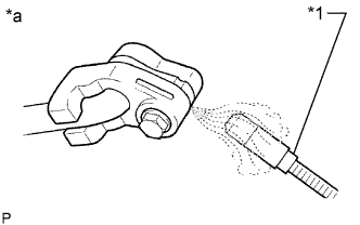
Text in Illustration *1 Halogen Leak Detector *a Check for Leakage Using a halogen leak detector, check the refrigerant line for leakage.
-
If a gas leak is not detected on the drain hose, remove the blower motor control (blower resistor) from the cooling unit. Insert the halogen leak detector sensor into the unit and perform the test.
-
Disconnect the connector and wait for approximately 20 minutes. Bring the halogen leak detector close to the pressure switch and perform the test.
-