COMPRESSOR (for 1KD-FTV) INSTALLATION

-
INSTALL COOLER COMPRESSOR ASSEMBLY
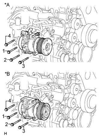
Text in Illustration *A except Cold Area Specification Vehicles *B for Cold Area Specification Vehicles
-
Temporarily install the cooler compressor with the 4 bolts.
Tech Tips
Tighten the bolts in the order shown in the illustration.
-
Tighten the 4 bolts.
- Torque:
- 25 N*m { 255 kgf*cm, 18 ft.*lbf }
Note
Tighten the bolts in the order shown in the illustration to install the cooler compressor.
-
-
INSTALL NO. 1 COOLER REFRIGERANT SUCTION HOSE
-
Remove the attached vinyl tape from the hose.
-
Sufficiently apply compressor oil to a new O-ring and the fitting surface of the cooler compressor.
Compressor oil ND-OIL 8 or equivalent -
Install the O-ring to the suction hose.
-
Connect the suction hose to the cooler compressor with the bolt.
- Torque:
- 9.8 N*m { 100 kgf*cm, 87 in.*lbf }
-
-
INSTALL NO. 1 COOLER REFRIGERANT DISCHARGE HOSE
-
Remove the attached vinyl tape from the hose.
-
Sufficiently apply compressor oil to a new O-ring and the fitting surface of the cooler compressor.
Compressor oil ND-OIL 8 or equivalent -
Install the O-ring to the discharge hose.
-
Connect the discharge hose to the cooler compressor with the bolt.
- Torque:
- 9.8 N*m { 100 kgf*cm, 87 in.*lbf }
-
-
INSTALL NO. 1 VISCOUS HEATER BRACKET SUB-ASSEMBLY (w/ Viscous Heater)
-
Install the No. 1 viscous heater bracket with the 4 bolts.
- Torque:
- 45 N*m { 459 kgf*cm, 33 ft.*lbf }
-
-
INSTALL VISCOUS WITH MAGNET CLUTCH HEATER ASSEMBLY (w/ Viscous Heater)
-
Install the viscous with magnet clutch heater assembly with the 2 bolts.
- Torque:
- 45 N*m { 459 kgf*cm, 33 ft.*lbf }
-
Connect the water by-pass hose and water hose.
-
Using pliers, grip the claws of the clips and slide the 2 clips.
-
Connect the viscous heater connector.
-
-
INSTALL FAN AND GENERATOR V BELT
-
Use the pulley set bolt of the tensioner to rotate the tensioner pulley clockwise, and then install the V belt.
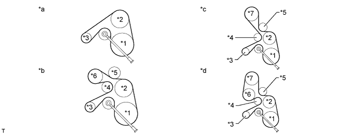
Text in Illustration *1 Crankshaft Pulley *2 Fan Pulley *3 Generator *4 No. 2 Idler Pulley *5 No. 3 Idler Pulley *6 Cooler Compressor *7 Viscous Heater - - *a Type A *b Type C *c Type B *d Type D Note
Make sure that the V belt is set properly on each pulley.
-
Check that the indicator mark of the V-ribbed belt tensioner Click here.
-
-
INSTALL COMPRESSOR OUTLET ELBOW
-
Install the compressor outlet elbow with the 2 bolts and tighten the hose clamp.
- Torque:
- for bolt
- 20 N*m { 204 kgf*cm, 15 ft.*lbf }
- for hose clamp
- 6.5 N*m { 66 kgf*cm, 58 in.*lbf }
-
Install the wire harness bracket with the bolt.
- Torque:
- 8.0 N*m { 82 kgf*cm, 71 in.*lbf }
-
Attach the 3 wire harness clamps.
-
-
INSTALL AIR CLEANER CASE SUB-ASSEMBLY
-
Install the air cleaner case with the 3 bolts.
- Torque:
- 12 N*m { 122 kgf*cm, 9 ft.*lbf }
-
-
INSTALL AIR CLEANER FILTER ELEMENT SUB-ASSEMBLY
-
INSTALL AIR CLEANER CAP SUB-ASSEMBLY
-
Install the air cleaner case with the 3 bolts.
- Torque:
- 12 N*m { 122 kgf*cm, 9 ft.*lbf }
-
-
INSTALL NO. 1 AIR CLEANER HOSE
-
Install the No. 1 air cleaner hose.
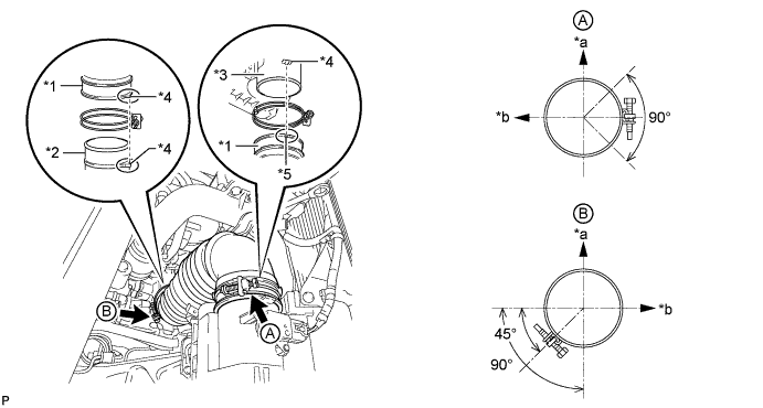
Text in Illustration *1 No. 1 Air Cleaner Hose *2 Compressor Inlet Elbow *3 Air Cleaner Cap *4 Protrusion *5 Groove - - *a Upper Side *b Front Side of Vehicle Note
-
When installing the No. 1 air cleaner hose, align its protrusion with the protrusion of the compressor inlet elbow as shown in the illustration.
-
When installing the No. 1 air cleaner hose, align its groove with the protrusion of the air cleaner cap as shown in the illustration.
-
-
Tighten the 2 hose clamps.
- Torque:
- 5.0 N*m { 51 kgf*cm, 44 in.*lbf }
Note
When tightening the 2 hose clamps, make sure that they are positioned as shown in the illustration.
-
-
INSTALL BATTERY TRAY
-
INSTALL BATTERY
-
INSTALL BATTERY HOLD DOWN CLAMP
-
Install the battery hold down clamp with the 2 nuts.
- Torque:
- 6.0 N*m { 61 kgf*cm, 53 in.*lbf }
-
-
INSTALL RADIATOR RESERVOIR
-
Connect the No. 2 water by-pass hose to the radiator reservoir.
-
Connect the No. 1 water by-pass hose to the fan shroud and attach the 2 clamps.
-
Install the radiator reservoir assembly with the 3 bolts.
- Torque:
- 5.0 N*m { 51 kgf*cm, 44 in.*lbf }
-
-
CONNECT CABLE TO NEGATIVE BATTERY TERMINAL
Note
When disconnecting the cable, some systems need to be initialized after the cable is reconnected Click here.
-
ADD ENGINE COOLANT
-
Tighten the radiator drain cock plug by hand.
-
Tighten the cylinder block drain cock plug.
- Torque:
- 8.0 N*m { 82 kgf*cm, 71 in.*lbf }
-
Fill the radiator with TOYOTA Super Long Life Coolant (SLLC) to the B line of the reservoir tank.
Standard Capacity Item Specified Condition for Automatic Transmission w/ Rear Heater 14.9 liters (15.7 US qts, 13.1 Imp. qts) w/o Rear Heater 13.1 liters (13.8 US qts, 11.5 Imp. qts) for Manual Transmission w/ Rear Heater 15.0 liters (15.8 US qts, 13.2 Imp. qts) w/o Rear Heater 13.2 liters (13.9 US qts, 11.6 Imp. qts) Tech Tips
-
TOYOTA vehicles are filled with TOYOTA SLLC at the factory. In order to avoid damage to the engine cooling system and other technical problems, only use TOYOTA SLLC or similar high quality ethylene glycol based non-silicate, non-amine, non-nitrite, non-borate coolant with long-life hybrid organic acid technology (coolant with long-life hybrid organic acid technology consists of a combination of low phosphates and organic acids).
-
Please contact your TOYOTA dealer for further details.
-
for Cold Area Specification Vehicles:
Please contact any authorized TOYOTA dealer or repairer or another duly qualified and equipped professional for further details.
Note
Never use water as a substitute for engine coolant.
-
-
Press the inlet and outlet radiator hoses several times by hand, and then check the level of the coolant.
If the coolant level drops below the B line, add TOYOTA SLLC to the B line.
-
Install the radiator reservoir cap.
-
Using a wrench, install the vent plug.
- Torque:
- 2.0 N*m { 20 kgf*cm, 18 in.*lbf }
-
Bleed air from the cooling system.
-
Warm up the engine until the thermostat opens. While the thermostat is open, circulate the coolant for several minutes.
-
Maintain the engine speed at 2500 to 3000 rpm.
-
Press the inlet and outlet radiator hoses several times by hand to bleed air.
CAUTION:
When pressing the radiator hoses:
-
Wear protective gloves.
-
Be careful as the radiator hoses are hot.
-
Keep your hands away from the radiator fan.
-
-
Stop the engine and wait until the coolant cools down to ambient temperature.
CAUTION:
Do not remove the radiator reservoir cap while the engine and radiator are still hot. Pressurized, hot engine coolant and steam may be released and cause serious burns.
-
-
After the coolant cools down, check that the coolant level is at the FULL line.
If the coolant level is below the FULL line, add TOYOTA SLLC to the FULL line.
-
-
INSTALL NO. 1 ENGINE UNDER COVER SUB-ASSEMBLY
-
Install the No. 1 engine under cover with the 4 bolts.
- Torque:
- 29 N*m { 296 kgf*cm, 21 ft.*lbf }
-
-
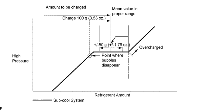
CHARGE REFRIGERANT
- SST
- 09985-20010 ( 09985-02130, 09985-02150, 09985-02090, 09985-02110, 09985-02010, 09985-02050, 09985-02060, 09985-02070 )
-
Perform vacuum purging using a vacuum pump.
-
Charge refrigerant HFC-134a (R134a).
Standard Model Code Air Conditioning Type Cool Box Refrigerant Charging Amount Except the model codes below w/o Rear Cooler w/ Cool Box 600 +/-30 g (21.2 +/-1.1 oz.) w/o Cool Box 550 +/-30 g (19.3 +/-1.1 oz.) w/ Rear Cooler w/ Cool Box 800 +/-30 g (28.2 +/-1.1 oz.) w/o Cool Box 770 +/-30 g (27.2 +/-1.1 oz.) w/ Rear Cooler
for Cold Area Specification Vehicles
w/o Cool Box 720 +/-30 g (25.3 +/-1.1 oz.) TRJ150L-GKMEKV
TRJ150L-GKPEKV
TRJ155L-GJPEKV
GRJ150L-GKFEKV
GRJ150L-GKAEKV
KDJ150L-GKFEYV
KDJ150L-GKAEYV
w/o Rear Cooler w/ Cool Box 600 +/-30 g (21.2 +/-1.1 oz.) w/o Cool Box 550 +/-30 g (19.3 +/-1.1 oz.) or 600 +/-30 g (21.2 +/-1.1 oz.) *1 w/ Rear Cooler w/ Cool Box 800 +/-30 g (28.2 +/-1.1 oz.) w/o Cool Box 770 +/-30 g (27.2 +/-1.1 oz.) *1: For vehicles with the 2TR-FE engine which have neither the rear cooler nor cool box, the refrigerant charging amount changes based on region.
Note
-
Do not operate the cooler compressor before charging refrigerant as the cooler compressor will not work properly without any refrigerant, and will overheat.
-
Approximately 100 g (3.53 oz.) of refrigerant may need to be charged after bubbles disappear. The refrigerant amount should be checked by measuring its quantity, and not with the sight glass.
-
-
WARM UP ENGINE
-
Warm up the engine at less than 1850 rpm for 2 minutes or more after charging the refrigerant.
Note
Be sure to warm up the compressor when turning the A/C switch is on after removing and installing the cooler refrigerant lines (including the compressor), to prevent damage to the compressor.
-
-
CHECK FOR REFRIGERANT GAS LEAK
-
After recharging the refrigerant gas, check for refrigerant gas leakage using a halogen leak detector.
-
Perform the operation under these conditions:
-
Stop the engine.
-
Secure good ventilation (the halogen leak detector may react to volatile gases other than refrigerant, such as evaporated gasoline or exhaust gas).
-
Repeat the test 2 or 3 times.
-
Make sure that some refrigerant remains in the refrigeration system. When compressor is off: approximately 392 to 588 kPa (4.0 to 6.0 kgf/cm2, 57 to 85 psi).
-
-
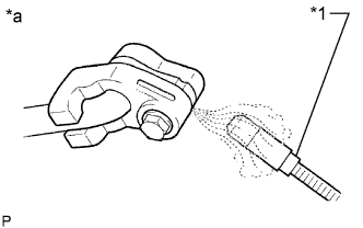
Text in Illustration *1 Halogen Leak Detector *a Check for Leakage Using a halogen leak detector, check the refrigerant line for leakage.
-
If a gas leak is not detected on the drain hose, remove the blower motor control (blower resistor) from the cooling unit. Insert the halogen leak detector sensor into the unit and perform the test.
-
Disconnect the connector and wait for approximately 20 minutes. Bring the halogen leak detector close to the pressure switch and perform the test.
-
-
INSTALL UPPER RADIATOR SUPPORT SEAL
-
Install the upper radiator support seal with the 13 clips.
-