COMPRESSOR (for 1KD-FTV) REASSEMBLY

-
INSTALL MAGNETIC CLUTCH ASSEMBLY
-
Place the cooler compressor in a vise.
-
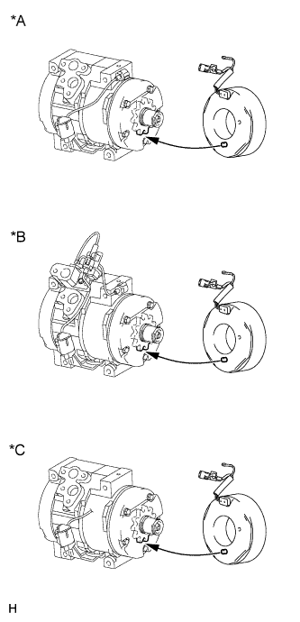
Install the magnet clutch stator with the parts shown in the illustration aligned.
Text in Illustration *A except Model Code KDJ150L-GKFEYV, KDJ150L-GKAEYV *B Model Code KDJ150L-GKFEYV, KDJ150L-GKAEYV *C for Cold Area Specification Vehicles -
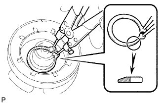
Using a snap ring expander, install a new snap ring with the chamfered side facing up.
Note
Take care not to damage the seal cover of the bearing when installing the snap ring.
-
Connect the connector.
-
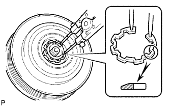
Using a snap ring expander, install the magnet clutch rotor and a new snap ring with the chamfered side facing up.
Note
-
Do not expand the snap ring by more than 30.5 mm (1.20 in.) when installing it.
-
Do not damage the seal cover of the bearing when installing the snap ring.
-
-
Install the magnet clutch washer and magnet clutch hub.
Note
Do not change the combination of the magnet clutch washers used before disassembly.
-
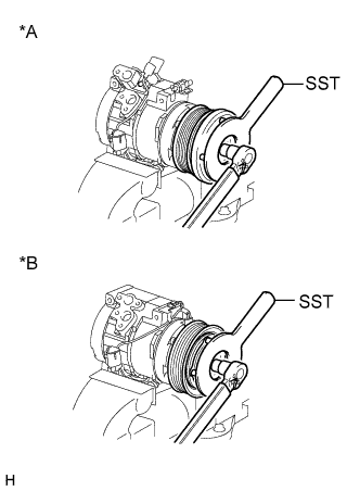
Text in Illustration *A except Cold Area Specification Vehicles *B for Cold Area Specification Vehicles Using SST, install the magnet clutch hub and magnet clutch washers with the bolt.
- SST
- 09985-00270
- Torque:
- 18 N*m { 184 kgf*cm, 13 ft.*lbf }
Note
Make sure that there is no foreign matter or oil on the compressor shaft, bolt and clutch hub.
-
-
INSTALL COOLER COMPRESSOR BRACKET
-
Install the cooler bracket with the screw.
-
Attach the clamp.
-
-
INSPECT MAGNETIC CLUTCH CLEARANCE
-
Set a dial indicator to the magnet clutch hub.
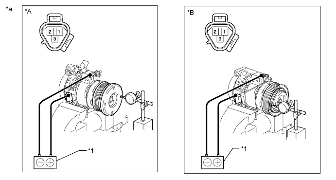
Text in Illustration *A except Cold Area Specification Vehicles *B for Cold Area Specification Vehicles *1 Battery - - *a Component without harness connected
(Magnet Clutch Assembly)
- - -
Connect the battery positive (+) lead to terminal 3 of the magnet clutch connector. Turn the magnet clutch on and off by connecting and disconnecting the battery negative (-) lead to and from the ground wire and measure the clearance.
Standard clearance 0.35 to 0.60 mm (0.013 to 0.024 in.) If the measured value is not within the standard range, remove the magnet clutch hub and adjust it with magnet clutch washers.
Note
Adjustment should be performed with 3 magnet clutch washers or less.
-
-
ADJUST COMPRESSOR OIL
-
When replacing the compressor and magnetic clutch with a new one, gradually discharge the refrigerant gas from the service valve and drain the following amount of oil from the new cooler compressor before installation.
Standard for Single Air Conditioning System: (The amount of oil inside a new cooler compressor: 120 to 135 cc (4.1 to 4.6 fl. oz.)) - (The amount of oil remaining in the removed cooler compressor) = (The amount of oil to be removed when replacing the compressor) for Dual Air Conditioning System (The amount of oil inside a new cooler compressor: 180 to 195 cc (6.1 to 6.6 fl. oz.)) - (The amount of oil remaining in the removed cooler compressor) = (The amount of oil to be removed when replacing the compressor) Note
-
When checking the compressor oil level, follow the A/C system precautions.
-
Since compressor oil remains in the pipes of the vehicle, if a new compressor is installed without removing some oil from the compressor, the oil amount becomes excessive. Excessive oil prevents heat exchange in the refrigerant cycle and causes refrigeration system failure.
-
If the volume of oil remaining in the removed cooler compressor is small, check for oil leakage.
-
Be sure to use ND-OIL 8 for compressor oil.
-
-