COMPRESSOR (for 1KD-FTV) REMOVAL

-
REMOVE UPPER RADIATOR SUPPORT SEAL
-
Remove the 13 clips and upper radiator support seal.
-
-
DISCONNECT CABLE FROM NEGATIVE BATTERY TERMINAL
Note
-
After turning the ignition switch off, waiting time may be required before disconnecting the cable from the battery terminal. Therefore, make sure to read the disconnecting the cable from the battery terminal notice before proceeding with work. Click here
-
When disconnecting the cable, some systems need to be initialized after the cable is reconnected Click here.
-
-
RECOVER REFRIGERANT FROM REFRIGERATION SYSTEM
-
Start the engine.
-
Operate the cooler compressor under the conditions shown below:
Item Condition Engine Speed Idling Operating Time 3 minutes or more A/C Switch Status On Blower Switch Status HI Set Temperature MAX COOL This causes most of the compressor oil from the various components of the A/C system to collect in the A/C compressor.
Note
It is not necessary to operate the cooler compressor if the A/C does not operate because of compressor lock, etc.
-
Stop the engine.
-
Recover the refrigerant from the A/C system using a refrigerant recovery unit.
Tech Tips
Use the refrigerant recovery unit in accordance with the manufacturer's instruction manual.
-
-
REMOVE NO. 1 ENGINE UNDER COVER SUB-ASSEMBLY
-
Remove the 4 bolts and No. 1 engine under cover.
-
-
DRAIN ENGINE COOLANT
CAUTION:
Do not remove the radiator cap while the engine and radiator are still hot. Pressurized, hot engine coolant and steam may be released and cause serious burns.
-
Loosen the radiator drain cock plug.
Tech Tips
Collect the coolant in a container and dispose of it according to the regulations in your area.
-
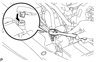
Drain the coolant by removing the reservoir cap and, using a wrench, remove the vent plug.
-
Loosen the cylinder block drain cock plug.
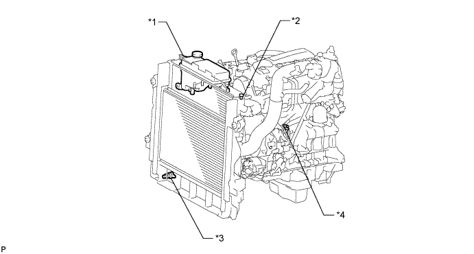
Text in Illustration *1 Radiator Reservoir *2 Vent Plug *3 Radiator Drain Cock Plug *4 Cylinder Block Drain Cock Plug
-
-
REMOVE RADIATOR RESERVOIR
-
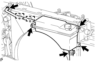
Disconnect the No. 1 water by-pass hose and detach the 2 clamps from the fan shroud.
-
Disconnect the No. 2 water by-pass hose from the radiator reservoir.
-
Remove the 3 bolts and radiator reservoir.
-
-
REMOVE BATTERY HOLD DOWN CLAMP
-
Remove the 2 nuts and battery hold down clamp.
-
-
REMOVE BATTERY
-
REMOVE BATTERY TRAY
-
REMOVE NO. 1 AIR CLEANER HOSE
-
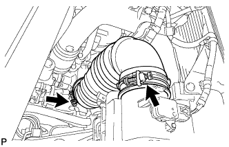
Loosen the 2 hose clamps and remove the No. 1 air cleaner hose.
-
-
REMOVE AIR CLEANER CAP SUB-ASSEMBLY
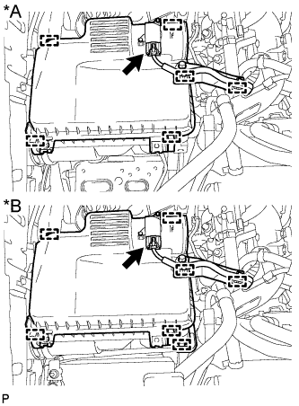
Text in Illustration *A except Cold Area Specification Vehicles *B for Cold Area Specification Vehicles
-
except Cold Area Specification Vehicles:
Detach the 2 clamps and disconnect the mass air flow meter connector.
-
for Cold Area Specification Vehicles:
Detach the 3 clamps and disconnect the mass air flow meter connector.
-
Detach the 4 clamps and remove the air cleaner cap.
-
-
REMOVE AIR CLEANER FILTER ELEMENT SUB-ASSEMBLY
-
REMOVE AIR CLEANER CASE SUB-ASSEMBLY
-
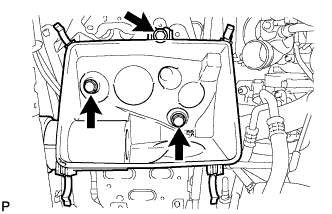
Remove the 3 bolts and air cleaner case.
-
-
REMOVE FAN AND GENERATOR V BELT
-
Using the pulley set bolt of the tensioner, rotate the tensioner pulley clockwise to loosen the belt tension. Then remove the V belt.
-
-
REMOVE COMPRESSOR OUTLET ELBOW
-
Detach the 3 wire harness clamps.
-
Remove the bolt and wire harness bracket.
-
Loosen the hose clamp and remove the 2 bolts and compressor outlet elbow.
-
-
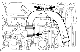
REMOVE VISCOUS WITH MAGNET CLUTCH HEATER ASSEMBLY (for Cold Area Specification Vehicles)
-
Disconnect the viscous heater connector.
-
Using pliers, grip the claws of the clips and slide the 2 clips.
-
Disconnect the water by-pass hose and water hose.
-
Remove the 2 bolts and heater assembly.
-
-
REMOVE NO. 1 VISCOUS HEATER BRACKET SUB-ASSEMBLY (for Cold Area Specification Vehicles)
-
Remove the 4 bolts and No. 1 viscous heater bracket.
-
-
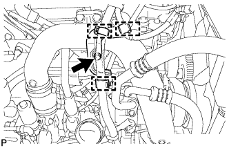
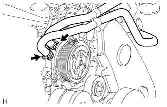
REMOVE NO. 1 COOLER REFRIGERANT DISCHARGE HOSE
-
Text in Illustration *A except Model Code KDJ150L-GKFEYV, KDJ150L-GKAEYV for LHD *B Model Code KDJ150L-GKFEYV, KDJ150L-GKAEYV *C for Cold Area Specification Vehicles Remove the bolt and disconnect the discharge hose from the cooler compressor.
-
Remove the O-ring from the discharge hose.
Note
Seal the openings of the disconnected parts using vinyl tape to prevent moisture and foreign matter from entering them.
-
-
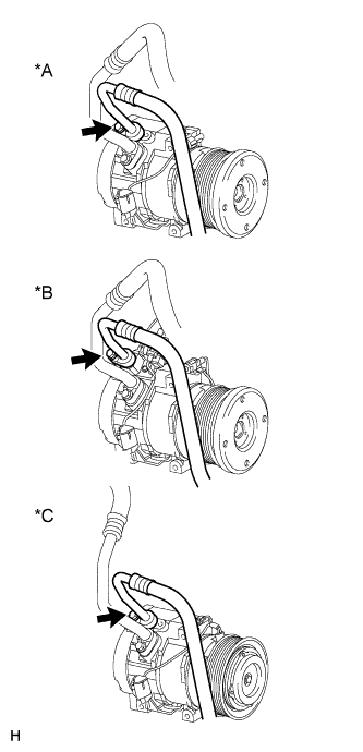
REMOVE NO. 1 COOLER REFRIGERANT SUCTION HOSE
-
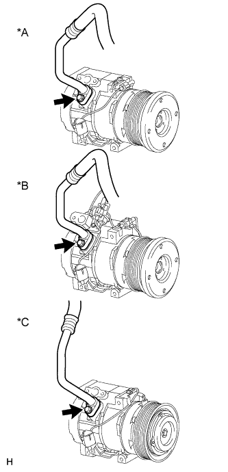
Text in Illustration *A except Model Code KDJ150L-GKFEYV, KDJ150L-GKAEYV for LHD *B Model Code KDJ150L-GKFEYV, KDJ150L-GKAEYV *C for Cold Area Specification Vehicles Remove the bolt and disconnect the suction hose.
-
Remove the O-ring from the suction hose.
Note
Seal the openings of the disconnected parts using vinyl tape to prevent moisture and foreign matter from entering them.
-
-
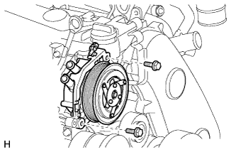
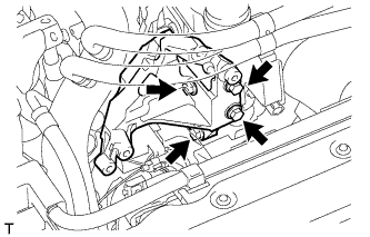
REMOVE COOLER COMPRESSOR ASSEMBLY
-
Disconnect the connector.
-
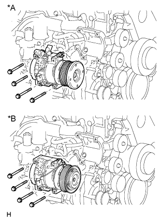
Text in Illustration *A except Cold Area Specification Vehicles *B for Cold Area Specification Vehicles Remove the 4 bolts and cooler compressor.
-