FRONT AIR CONDITIONING UNIT REMOVAL

Tech Tips
-
Use the same procedure for RHD and LHD vehicles.
-
The procedure listed below is for LHD vehicles.
-
RECOVER REFRIGERANT FROM REFRIGERATION SYSTEM
-
Start the engine.
-
Operate the cooler compressor under the conditions shown below:
Item Condition Engine Speed Idling Operating Time 3 minutes or more A/C Switch Status On Blower Switch Status HI Set Temperature MAX COOL This causes most of the compressor oil from the various components of the A/C system to collect in the A/C compressor.
Note
It is not necessary to operate the cooler compressor if the A/C does not operate because of compressor lock, etc.
-
Stop the engine.
-
Recover the refrigerant from the A/C system using a refrigerant recovery unit.
Tech Tips
Use the refrigerant recovery unit in accordance with the manufacturer's instruction manual.
-
-
DRAIN ENGINE COOLANT
-
for 1GR-FE:
Drain the engine coolant Click here.
-
for 1KD-FTV:
Drain the engine coolant Click here.
-
for 2TR-FE:
Drain the engine coolant Click here.
-
for 5L-E:
Drain the engine coolant Click here.
-
-
DISCONNECT CABLE FROM NEGATIVE BATTERY TERMINAL
CAUTION:
Wait at least 90 seconds after disconnecting the cable from the negative (-) battery terminal to disable the SRS system.
Note
-
After turning the ignition switch off, waiting time may be required before disconnecting the cable from the battery terminal. Therefore, make sure to read the disconnecting the cable from the battery terminal notice before proceeding with work. Click here
-
When disconnecting the cable, some systems need to be initialized after the cable is reconnected Click here.
-
-
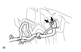
DISCONNECT AIR CONDITIONING TUBE AND ACCESSORY ASSEMBLY (for Bolt Joint Type)
-
Remove the 2 bolts.
-
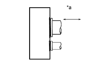
Text in Illustration *a Disconnect tube by hand Disconnect the air conditioning tube and accessory assembly.
Note
-
Do not use a screwdriver or similar tool to disconnect the tube.
-
Seal the openings of the disconnected parts using vinyl tape to prevent moisture and foreign matter from entering them.
-
-
Remove the grommet.
-
Remove the 2 O-rings from the air conditioning tube and accessory assembly.
-
-
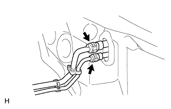
DISCONNECT AIR CONDITIONING TUBE AND ACCESSORY ASSEMBLY (for Quick Joint Type)
-
Using SST, remove the piping clamp.
-
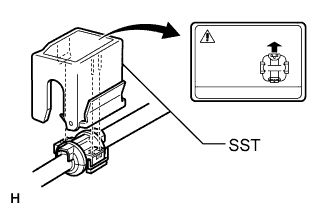
Attach SST to the piping clamp.
- SST
- 09870-00015
- 09870-00025
Tech Tips
Confirm the direction of the piping clamp claw and SST by referring to the illustration on the caution label.
-
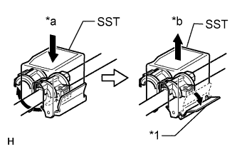
Text in Illustration *1 Release Lever *a Push *b Pull Push down SST and release the clamp lock.
Note
Be careful not to deform the tubes when pushing SST.
-
Pull SST slightly and push the release lever, then remove the piping clamp with SST.
-
Remove the piping clamp from SST.
-
Disconnect the air conditioning tube and accessory assembly.
Note
Cap the open fittings immediately to keep moisture or dirt out of the system.
-
-
Remove the grommet.
-
-
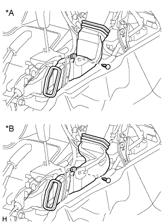
DISCONNECT HEATER WATER INLET HOSE AND HEATER WATER OUTLET HOSE
-
Using pliers, grip the claws of the clips and slide the 2 clips.
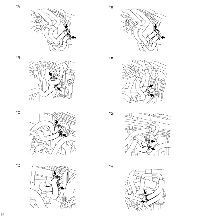
Text in Illustration *A for 1GR-FE, for Single Air Conditioning System *B for 1KD-FTV, for Single Air Conditioning System *C for 5L-E, for Single Air Conditioning System *D for 2TR-FE, for Single Air Conditioning System *E for 1GR-FE, for Dual Air Conditioning System *F for 1KD-FTV, for Dual Air Conditioning System *G for 5L-E, for Dual Air Conditioning System *H for 2TR-FE, for Dual Air Conditioning System -
Disconnect the 2 heater water hoses.
-
-
REMOVE WINDSHIELD WIPER MOTOR ASSEMBLY
-
Remove the windshield wiper motor assembly Click here.
-
-
REMOVE INSTRUMENT PANEL SUB-ASSEMBLY
-
Remove the instrument panel sub-assembly Click here.
-
-
REMOVE STEERING COLUMN ASSEMBLY
-
for Power Tilt and Power Telescopic Steering Column:
Remove the steering column assembly Click here.
-
for Manual Tilt and Manual Telescopic Steering Column:
Remove the steering column assembly Click here.
-
-
REMOVE FRONT SEAT ASSEMBLY LH
-
for Manual Seat:
Remove the front seat assembly LH Click here.
-
for Power Seat:
Remove the front seat assembly LH Click here.
-
for Walk in Seat Type:
Remove the front seat assembly LH Click here.
-
for Bench Seat Type:
Remove the front seat assembly LH Click here.
-
-
REMOVE FRONT SEAT ASSEMBLY RH
-
for Manual Seat:
Remove the front seat assembly RH Click here.
-
for Power Seat:
Remove the front seat assembly RH Click here.
-
for Walk in Seat Type:
Remove the front seat assembly RH Click here.
-
for Bench Seat Type:
Remove the front seat assembly RH Click here.
-
-
REMOVE FRONT FLOOR CARPET ASSEMBLY
Note
It is not necessary to fully remove the floor carpet. Partially remove it so that the rear air duct can be removed in a later step.
-
REMOVE REAR NO. 3 AIR DUCT
-
Detach the 3 clamps and 6 claws and remove the rear No. 3 air duct.
-
-
REMOVE REAR NO. 1 AIR DUCT
-
Detach the 3 clamps and 6 claws and the rear No. 1 air duct.
-
-
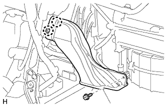
REMOVE NO. 1 CONSOLE BOX DUCT
-
Text in Illustration *A Automatic Transmission *B Manual Transmission Remove the clip and No. 1 console box duct.
-
-
REMOVE NO. 1 INSTRUMENT PANEL BRACE MOUNTING BRACKET LH
-
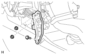
Remove the 2 nuts, bolt and No. 1 instrument panel brace mounting bracket LH.
-
-
REMOVE NO. 1 INSTRUMENT PANEL BRACE MOUNTING BRACKET RH
-
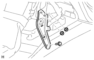
Remove the 2 nuts, bolt and No. 1 instrument panel brace mounting bracket RH.
-
-
REMOVE NO. 1 AIR DUCT SUB-ASSEMBLY
-
Detach the 3 claws and No. 1 air duct sub-assembly.
-
-
REMOVE NO. 2 AIR DUCT SUB-ASSEMBLY
-
Remove the screw.
-
Detach the 2 claws and remove the No. 2 air duct sub-assembly.
-
-
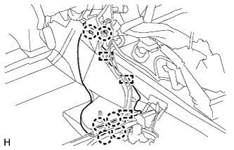
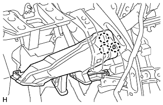
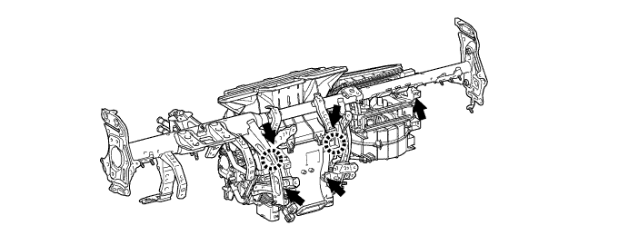
REMOVE INSTRUMENT PANEL REINFORCEMENT ASSEMBLY WITH AIR CONDITIONING UNIT ASSEMBLY
-
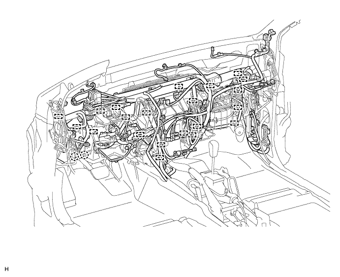
Disconnect the clamps and connectors.
-
Remove the bolts, nuts and wire harness.
-
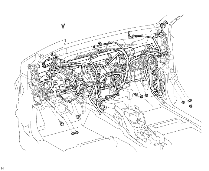
Remove the instrument panel reinforcement assembly with air conditioning unit assembly.
-
Remove the 5 caps.
-
Using a T40 "TORX" socket, remove the 5 "TORX" bolts.
-
Using a 12 mm hexagon wrench, loosen the 2 collars.
-
Remove the bolts, nuts and the instrument panel reinforcement assembly with air conditioning unit assembly.
-
-
-
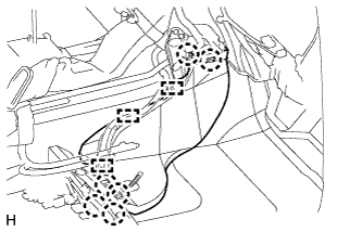
REMOVE INSTRUMENT PANEL REINFORCEMENT ASSEMBLY
-
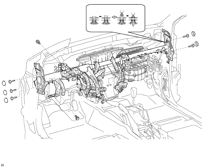
Detach the 2 claws and remove the 5 bolts and instrument panel reinforcement assembly.
-