AIR CONDITIONING SYSTEM (for Manual Air Conditioning System) Air Conditioning Compressor Magnetic Clutch Circuit
DESCRIPTION
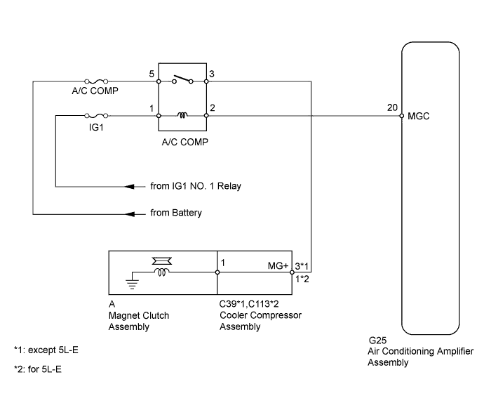
When the air conditioning amplifier assembly is turned on, a magnet clutch assembly ON signal is sent from the MGC terminal of the air conditioning amplifier assembly. Then, the A/C COMP relay turns on to operate the magnet clutch assembly.
WIRING DIAGRAM
INSPECTION PROCEDURE
Note
Inspect the fuses for circuits related to this system before performing the following inspection procedure.
PROCEDURE
-
INSPECT MAGNET CLUTCH RELAY (A/C COMP)
-
Remove the A/C COMP relay from the engine room No. 1 relay block, junction block.
-
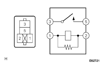
Measure the resistance according to the value(s) in the table below.
Standard Resistance Tester Connection Condition Specified Condition 3 - 5 Battery voltage is not applied to terminals 1 and 2 10 kΩ or higher Battery voltage is applied to terminals 1 and 2 Below 1 Ω
NG 
REPLACE MAGNET CLUTCH RELAY (A/C COMP)
OK 
-
-
INSPECT COOLER COMPRESSOR ASSEMBLY
-
except 5L-E:
-
Remove the cooler compressor assembly (for 1GR-FE) Click here.
-
Remove the cooler compressor assembly (for 1KD-FTV) Click here.
-
Remove the cooler compressor assembly (for 2TR-FE) Click here.
-
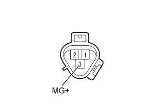
Disconnect the A magnet clutch connector.
-
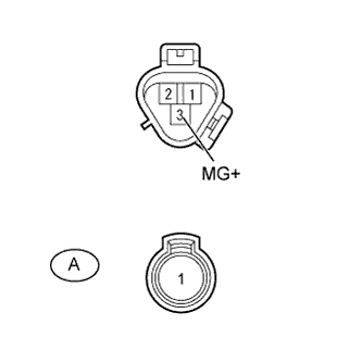
Measure the resistance according to the value(s) in the table below.
Standard Resistance Tester Connection Condition Specified Condition 3 (MG+) - A-1 Always Below 1 Ω 3 (MG+) - Body ground Always 10 kΩ or higher
-
-
for 5L-E:
-
Remove the cooler compressor assembly Click here.
-
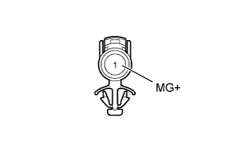
Disconnect the A magnet clutch connector.
-
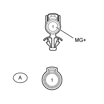
Measure the resistance according to the value(s) in the table below.
Standard Resistance Tester Connection Condition Specified Condition 1 (MG+) - A-1 Always Below 1 Ω 1 (MG+) - Body ground Always 10 kΩ or higher Result Result Proceed to OK A NG (for 1GR-FE) B NG (for 1KD-FTV) C NG (for 5L-E) D NG (for 2TR-FE) E
-
B
REPLACE COOLER COMPRESSOR ASSEMBLY Click here
C
REPLACE COOLER COMPRESSOR ASSEMBLY Click here
D
REPLACE COOLER COMPRESSOR ASSEMBLY Click here
E
REPLACE COOLER COMPRESSOR ASSEMBLY Click here
A
-
-
INSPECT MAGNET CLUTCH ASSEMBLY
-
except 5L-E:
-
Reconnect the A magnet clutch connector.
-
Apply battery voltage to the magnet clutch assembly and check the operation of the magnet clutch assembly.
OK Measurement Condition Specified Condition Battery positive (+) → Terminal 3 (MG+)
Battery negative (-) → Body ground
Magnet clutch assembly operating sound can be heard, and magnetic clutch hub and rotor lock.
-
-
for 5L-E:
-
Reconnect the A magnet clutch connector.
-
Apply battery voltage to the magnet clutch assembly and check the operation of the magnet clutch assembly.
OK Measurement Condition Specified Condition Battery positive (+) → Terminal 1 (MG+)
Battery negative (-) → Body ground
Magnet clutch assembly operating sound can be heard, and magnetic clutch hub and rotor lock. Result Result Proceed to OK A NG (for 1GR-FE) B NG (for 1KD-FTV) C NG (for 5L-E) D NG (for 2TR-FE) E
-
B
REPLACE MAGNET CLUTCH ASSEMBLY Click here
C
REPLACE MAGNET CLUTCH ASSEMBLY Click here
D
REPLACE MAGNET CLUTCH ASSEMBLY Click here
E
REPLACE MAGNET CLUTCH ASSEMBLY Click here
A
-
-
CHECK HARNESS AND CONNECTOR (ENGINE ROOM NO. 1 RELAY BLOCK, JUNCTION BLOCK - BATTERY)
-
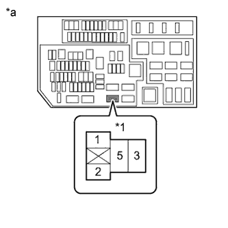
Text in Illustration *1 A/C COMP Relay *a Component without relay installed
(Engine Room No. 1 Relay Block, Junction Block)
Remove the A/C COMP relay from the engine room No. 1 relay block, junction block.
-
Measure the voltage according to the value(s) in the table below.
Standard Voltage Tester Connection Switch Condition Specified Condition A/C COMP relay terminal 1 - Body ground Ignition switch ON 11 to 14 V A/C COMP relay terminal 5 - Body ground Always 11 to 14 V
NG
REPAIR OR REPLACE HARNESS OR CONNECTOR
OK
-
-
CHECK HARNESS AND CONNECTOR (AIR CONDITIONING AMPLIFIER - BATTERY)
-
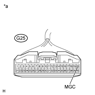
Text in Illustration *a Front view of wire harness connector
(to Air Conditioning Amplifier Assembly)
Disconnect the G25 amplifier connector.
-
Measure the voltage according to the value(s) in the table below.
Standard Voltage Tester Connection Switch Condition Specified Condition G25-20 (MGC) - Body ground Ignition switch off Below 1 V G25-20 (MGC) - Body ground Ignition switch ON 11 to 14 V
NG
REPAIR OR REPLACE HARNESS OR CONNECTOR
OK
-
-
CHECK HARNESS AND CONNECTOR (ENGINE ROOM NO. 1 RELAY BLOCK, JUNCTION BLOCK - COOLER COMPRESSOR)
-
Remove the A/C COMP relay from the engine room No. 1 relay block, junction block.
-
Disconnect the C39*1 or C113*2 compressor connector.
-
*1: except 5L-E
-
*2: for 5L-E
-
-
Measure the resistance according to the value(s) in the table below.
Standard Resistance except 5L-E Tester Connection Condition Specified Condition A/C COMP relay terminal 3 - C39-3 (MG+) Always Below 1 Ω C39-3 (MG+) - Body ground Always 10 kΩ or higher for 5L-E Tester Connection Condition Specified Condition A/C COMP relay terminal 3 - C113-1 (MG+) Always Below 1 Ω C113-1 (MG+) - Body ground Always 10 kΩ or higher
NG
REPAIR OR REPLACE HARNESS OR CONNECTOR
OK 
PROCEED TO NEXT SUSPECTED AREA SHOWN IN PROBLEM SYMPTOMS TABLE Click here
-