AIR CONDITIONING SYSTEM (for Manual Air Conditioning System) SYSTEM DESCRIPTION

-
GENERAL
-
The air conditioning system has the following controls.
Control Outline Manual Control The air conditioning amplifier assembly controls the damper positions (air inlet control damper, air mix control damper and mode control damper) and blower speed in accordance with the positions of the switches (temperature control dial, blower dial, mode operation switch and REC/FRS switch). Air Inlet Control Drives the recirculation damper servo sub-assembly according to the operation of the REC/FRS switch and moves the dampers to the fresh or recirculation position. Compressor Control The air conditioning amplifier assembly compares the A/C pulley speed signals, which are transmitted by the ECM (crankshaft position sensor). When the air conditioning amplifier assembly determines that the A/C pulley is locked, it turns off the magnet clutch assembly. Defroster Control Defroster control logic is used to improve defroster performance. Defroster Fresh Air Mode Switching Control Defroster fresh air mode switching control changes the system from recirculation air mode to fresh air mode to improve defroster performance. Rear Defogger Control When the ignition switch is ON and the rear defogger switch is pushed, the system is activated to keep the defogger heater on for approx. 15 minutes. However, the operating time of the rear defogger can be extended up to approx. 255 minutes when both of the following requirements are met:
-
Ambient Temperature: -3°C (26.6°F) or less
-
Vehicle Speed: 50 km/h (31.1 mph) or more
Diagnosis A Diagnostic Trouble Code (DTC) is stored in memory when the air conditioning amplifier assembly detects a problem with the air conditioning system. -
-
-
MODE POSITION AND DAMPER OPERATION
-
Mode Position and Damper Operation
-
Front Air Conditioning Unit
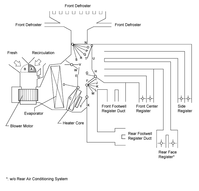
Function of Main Damper Control Damper Operation Position Damper Position Operation Air Inlet Control Damper Fresh A Brings in fresh air. Recirculation B Recirculates internal air. Air Mix Control Damper MAX COOL to MAX HOT E - D - C Varies the mixture of cold air and hot air in order to regulate the temperature continuously from hot to cool. MAX COOL Damper MAX COOL V Open in the MAX COOL position. Except MAX COOL W Close in all position except MAX COOL position. MAX HOT Damper MAX HOT Y Open in the MAX HOT position. Except MAX HOT X Closed in all position except MAX HOT position. Mode Control Damper 
Face
F, I, N, T, X Air blows out of the front center registers, side registers and rear face registers. 
Bi-level
G, L, N, T, X Air blows out of the front center registers, side registers, rear face registers and front and rear footwell register ducts. 
Foot
H, M, P, T, W, Y (MAX HOT position)
H, M, O, T, X (Except MAX HOT position)
Air blows out of the front and rear footwell register ducts.
In addition, air blows out slightly from the front defroster, side registers, front center registers and rear face registers.

Foot/Def
H, K, R, T, W, Y (MAX HOT position)
H, M, Q, T, X (Except MAX HOT position)
Defrosts the windshield through the front defroster and side registers while air is also blown out from the front and rear footwell register ducts.
In addition, air blows out slightly from the front center registers and rear face registers.

Def
H, I, S, U, X Defrosts the windshield through the front defrosters. -
Rear Air Conditioning Unit (w/ Rear Air Conditioning System)
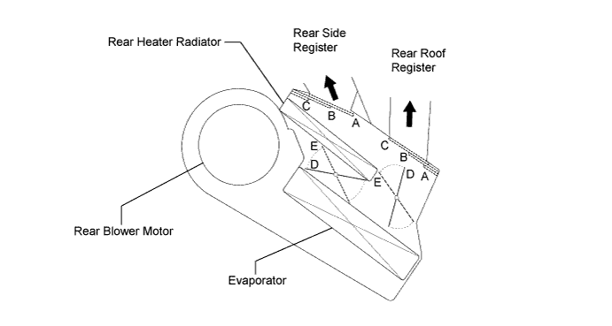
Function of Main Damper Control Damper Operation Position Damper Position Operation Mode Control Damper Face
A Air blows out from the rear roof registers. Bi-level
B Air blows out from the rear roof registers and rear side registers. Foot
C Air blows out from the rear side registers. Air Mix Control Damper MAX COLD to MAX HOT Temperature Setting D, E Varies the mixture of cold air and hot air in order to regulate the temperature continuously from hot to cold.
-
-
-
AIR OUTLETS AND AIRFLOW VOLUME
-
Air Outlets and Airflow Volume
-
for Front Registers
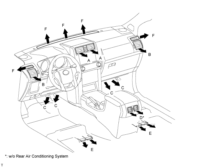
Indication
(Mode)
Front Center Register Side Register Front Footwell Register Rear Face Register Rear Footwell Register Front Defroster A B C D E F Face

- 
- - Bi-level

- Foot

Foot/Def
Def
- - - - - Tech Tips
-
The size of the circle indicates the proportion of airflow volume.
-
The same system is used for LHD and RHD vehicles.
-
-
for Rear Registers (w/ Rear Air Conditioning System)
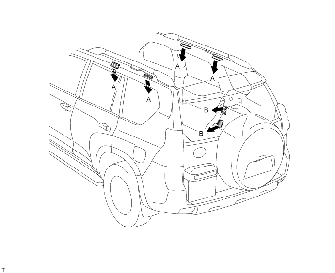
Indication
(Mode)
Rear Roof Register Rear Side Register A B Face
- Bi-level
Foot
- Tech Tips
The size of the circle ○ indicates the ratio of airflow volume.
-
-
-
A/C LOCK SENSOR (except 5L-E)
The A/C lock sensor sends A/C pulley speed signals to the air conditioning amplifier assembly. The air conditioning amplifier assembly determines whether the A/C compressor is locked or not by using those signals and engine speed signals.
-
No. 1 COOLER THERMISTOR
The No. 1 cooler thermistor detects the temperature of the cool air immediately after it passes through the evaporator in the form of resistance changes, and outputs the temperature to the air conditioning amplifier assembly.
-
BLOWER WITH FAN MOTOR SUB-ASSEMBLY
The blower with fan motor sub-assembly has a built-in blower controller, and is controlled by the air conditioning amplifier assembly using duty control.
-
AIR CONDITIONING HARNESS ASSEMBLY (BUS CONNECTOR)
-
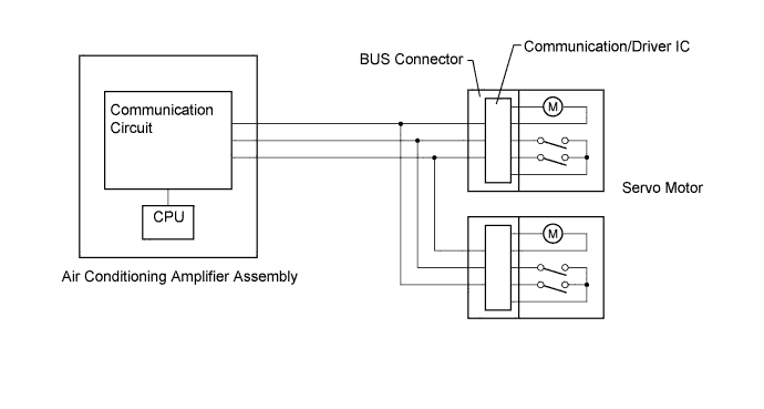
A BUS connector is used in the wire harness that connects the servo motor to the air conditioning amplifier assembly.
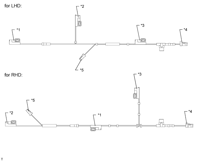
Connector Type Connected to *1: Bus connector Damper servo sub-assembly LH (mode damper servo) *2: Bus connector Damper servo sub-assembly RH (air mix damper servo) *3: Bus connector Recirculation damper servo sub-assembly *4: Bus connector Air conditioning amplifier assembly *5: Connector No. 1 cooler thermistor -
Each BUS connector has a built-in communication/driver IC which communicates with each servo motor connector, actuates the servo motor, and has a position detection function.
-
-
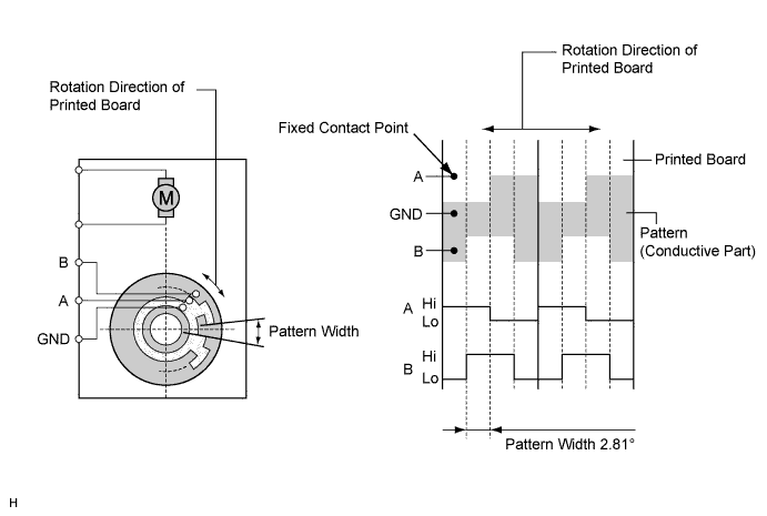
SERVO MOTOR
-
The pulse pattern type servo motor detects the relative position using 2-bit on/off signals.
The forward and reverse revolutions of this motor are detected using two signals, A and B, which output four types of patterns. The air conditioning amplifier assembly counts the number of pulse patterns in order to determine the stopped position.
-
-
COOLER THERMISTOR (AMBIENT TEMPERATURE SENSOR)
The cooler thermistor (ambient temperature sensor) detects the outside temperature based on changes in the resistance of its built-in thermistor and sends a signal to the air conditioning amplifier assembly.