FUEL PUMP (for 5 Door) REASSEMBLY

Note
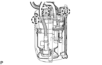
Do not disconnect the hoses indicated in the illustration.
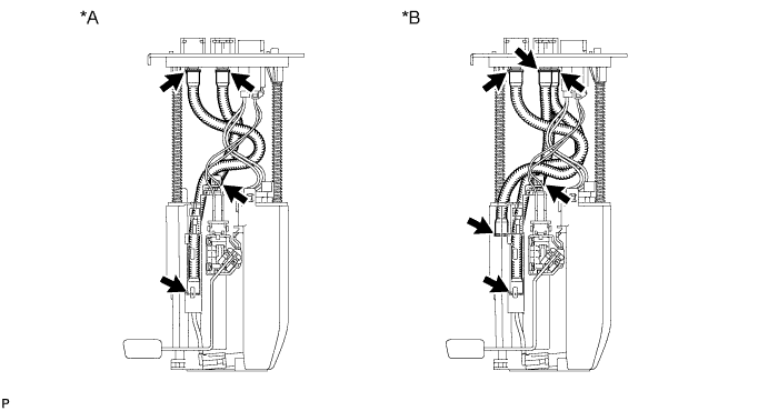
| *A | for Single Tank Type | *B | for Double Tank Type |
-
INSTALL FUEL SUCTION CAP
-
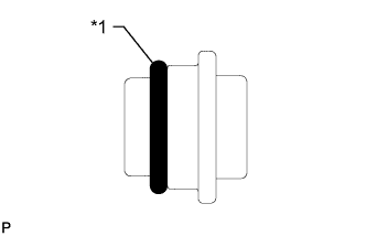
Text in Illustration *1 New O-Ring Apply a light coat of gasoline to a new O-ring and install the O-ring to the fuel suction cap.
-
Install the fuel suction cap to the fuel filter case.
Note
Make sure the O-ring is not cut or pinched during installation.
-
-
INSTALL FUEL PUMP
-
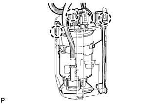
Connect the fuel pump wire harness connector to the fuel pump.
-
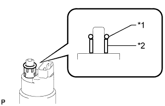
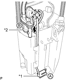
Text in Illustration *1 New O-Ring *2 Fuel Pump Spacer Apply a light coat of gasoline to a new O-ring. Then install the fuel pump spacer and O-ring to the fuel pump.
-
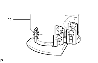
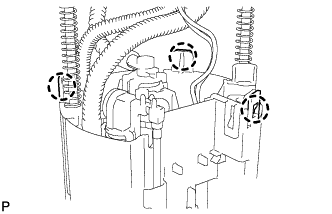
Text in Illustration *1 Fuel Filter Case Attach the 5 claws to the claw holes to install the fuel pump to the fuel filter case.
-
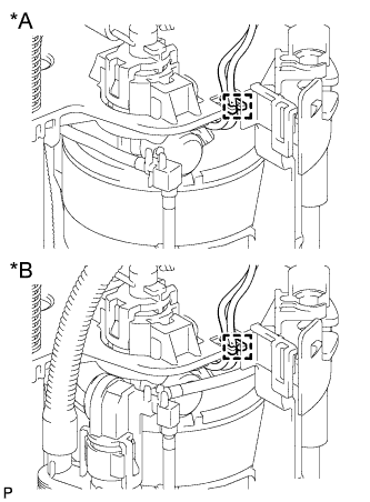
Text in Illustration *A for Single Tank Type *B for Double Tank Type Attach the fuel pump wire harness clamp.
-
-
INSTALL NO. 1 FUEL SUB-TANK (for Single Tank Type)
-
Attach the 3 claws to the claw holes to install the No. 1 fuel sub-tank.
-
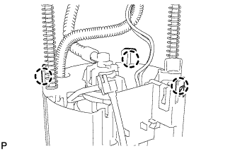
Attach the 3 claws to the claw holes.
-
Install the tube part to the No. 1 fuel sub-tank.
-
Attach the claw on the end of the tube to the claw hole. Install the tube to the 2 clamps on the No. 1 fuel sub-tank.
-
-
Connect the jet pump to the No. 1 fuel sub-tank.
Text in Illustration *1 Jet Pump -
Connect the fuel pump connector.
-
-
INSTALL NO. 1 FUEL SUB-TANK (for Double Tank Type)
-
Attach the 3 claws to the claw holes to install the No. 1 fuel sub-tank.
-
Attach the 3 claws to the claw holes.
-
Connect the jet pump labeled B to the No. 1 fuel sub-tank.
-
Text in Illustration *1 Jet Pump A *2 Jet Pump B Attach the claw on the end of the tube to the claw hole.
-
-
Connect the jet pump labeled A to the No. 1 fuel sub-tank.
-
Connect the fuel pump connector.
-
-
INSTALL FUEL SENDER GAUGE ASSEMBLY (for Single Tank Type)
-

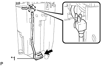
Text in Illustration *1 Fuel Sub-Tank 
Slide Set the fuel sender gauge on the fuel sub-tank. Then slide the fuel sender gauge downward to install it.
-
Connect the fuel sender gauge connector.
-
-
INSTALL FUEL SENDER GAUGE ASSEMBLY (for Double Tank Type)
-
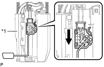
Text in Illustration *1 Fuel Sub-tank Slide Set the fuel sender gauge on the fuel sub-tank. Then slide the fuel sender gauge downward to install it.
-
Connect the fuel sender gauge connector.
-