CYLINDER BLOCK INSPECTION

-
INSPECT CYLINDER BLOCK FOR WARPAGE
-
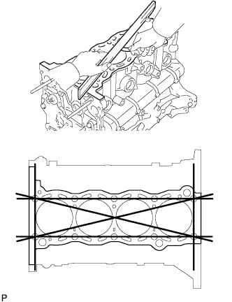
Using a precision straightedge and feeler gauge, measure the warpage of the surface that contacts the cylinder head gasket.
Maximum warpage 0.05 mm (0.00197 in.) If the warpage is more than the maximum, replace the cylinder block.
-
Visually check the cylinder for vertical scratches.
If deep scratches are present, rebore all 4 cylinders. If necessary, replace the cylinder block.
-
-
INSPECT CYLINDER BORE
-
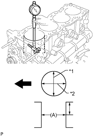
Text in Illustration *1 Thrust Direction *2 Axial Direction 
Front Using a cylinder gauge, measure the cylinder bore diameter at position A in the thrust and axial directions.
Standard diameter 94.990 to 95.003 mm (3.7398 to 3.7403 in.) Maximum difference in diameter 0.2 mm (0.00787 in.) Measurement position 70 mm (2.76 in.) If the diameter is more than the maximum, rebore all 4 cylinders. If necessary, replace the cylinder block.
-
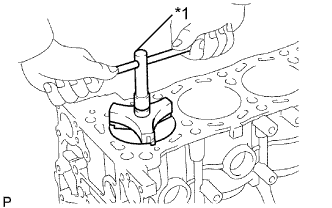
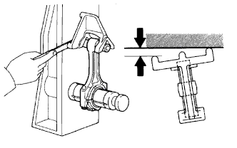
Text in Illustration *1 Ridge Reamer Inspect the cylinder ridge.
If the wear is less than 0.2 mm (0.00787 in.), using a ridge reamer, grind the top of the cylinder.
-
-
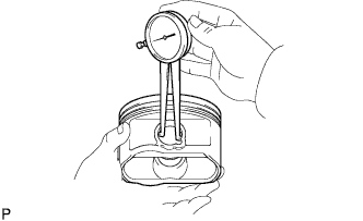
INSPECT PISTON DIAMETER
-
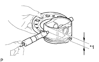
Text in Illustration *1 Distance Using a micrometer, measure the piston diameter at right angles to the piston center line where the distance from the piston end is as specified.
Distance 13.8 mm (0.543 in.) Standard diameter 94.941 to 94.971 mm (3.738 to 3.739 in.)
-
-
INSPECT PISTON OIL CLEARANCE
-
Measure the cylinder bore diameter in the thrust direction.
-
Subtract the piston diameter measurement from the cylinder bore diameter measurement.
Standard oil clearance 0.019 to 0.052 mm (0.000748 to 0.00205 in.) If the oil clearance is more than the standard, replace all the pistons and rebore all the cylinders. If necessary, replace the cylinder block.
-
-
INSPECT RING GROOVE CLEARANCE
-
Using a feeler gauge, measure the clearance between a new piston ring and the wall of the ring groove.
Standard Ring Groove Clearance Item Specified Condition No. 1 compression ring 0.020 to 0.075 mm (0.000787 to 0.00295 in.) No. 2 compression ring 0.020 to 0.065 mm (0.000787 to 0.00256 in.) Oil ring 0.020 to 0.070 mm (0.000787 to 0.00276 in.) If the groove clearance is not as specified, replace the piston with pin.
-
-
INSPECT PISTON RING END GAP
-
Insert the piston ring into the cylinder bore.
-
Using a piston, push the piston ring a little beyond the bottom of the ring travel, 110 mm (4.33 in.) from the top of the cylinder block.
-
Using a feeler gauge, measure the end gap.
Standard End Gap Item Specified Condition No. 1 compression ring 0.26 to 0.38 mm (0.0102 to 0.0150 in.) No. 2 compression ring 0.59 to 0.71 mm (0.0232 to 0.0280 in.) Oil ring 0.10 to 0.40 mm (0.00394 to 0.0157 in.) Maximum End Gap Item Specified Condition No. 1 compression ring 0.90 mm (0.0354 in.) No. 2 compression ring 1.36 mm (0.0535 in.) Oil ring 0.75 mm (0.0295 in.) If the end gap is more than the maximum, replace the piston ring. If the end gap is less than the standard, even with a new piston ring, rebore all 4 cylinders or replace the cylinder block.
-
-
INSPECT PISTON PIN OIL CLEARANCE
-
Using a caliper gauge, measure the inside diameter of the piston pin hole.
Standard piston pin hole inside diameter 22.001 to 22.010 mm (0.866 to 0.867 in.) If the diameter is not as specified, replace the piston with pin.
-
Using a micrometer, measure the piston pin diameter.
Measurement Position Measurement Position Piston Pin Position a 31 mm (1.22 in.) b 6 mm (0.24 in.) Standard piston pin diameter 21.997 to 22.009 mm (0.8660 to 0.8665 in.) If the diameter is not as specified, replace the piston with pin.
-
Subtract the piston pin diameter measurement from the piston pin hole diameter measurement.
Standard oil clearance 0.001 to 0.007 mm (0.0000394 to 0.000276 in.) Maximum oil clearance 0.010 mm (0.000394 in.) If the oil clearance is more than the maximum, replace the piston and piston pin as a set.
-
Using a caliper gauge, measure the inside diameter of the connecting rod bush.
Standard bush inside diameter 22.005 to 22.014 mm (0.866 to 0.867 in.) If the diameter is not as specified, replace the connecting rod small end bush.
-
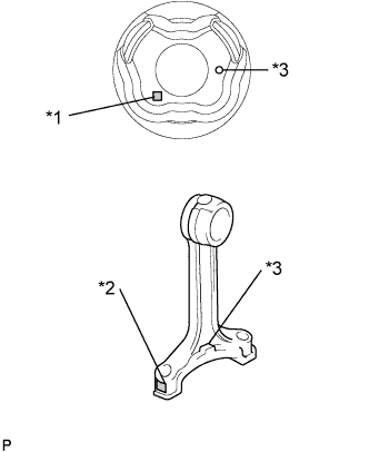
Text in Illustration *1 Piston Pin Hole Inside Diameter Mark *2 Connecting Rod Bushing Inside Diameter Mark *3 Front Mark Subtract the piston pin diameter measurement from the bush inside diameter measurement.
Standard oil clearance 0.005 to 0.011 mm (0.000197 to 0.000433 in.) Maximum oil clearance 0.025 mm (0.000984 in.) If the oil clearance is more than the maximum, replace the connecting rod small end bush. If necessary, replace the connecting rod and piston pin as a set.
-
-
INSPECT CONNECTING ROD SUB-ASSEMBLY
-
Using a rod aligner and feeler gauge, check the connecting rod alignment.
-
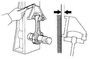
Check for bend.
Maximum bend 0.03 mm (0.00118 in.) per 100 mm (3.94 in.) If the bend is more than the maximum, replace the connecting rod sub-assembly.
-
Check for twist.
Maximum twist 0.15 mm (0.00591 in.) per 100 mm (3.94 in.) If the twist is more than the maximum, replace the connecting rod sub-assembly.
-
-
-
INSPECT CRANKSHAFT
-
Inspect the circle runout.
-
Place the crankshaft on V-blocks.
-
Using a dial indicator, measure the circle runout at the center journal.
Maximum circle runout 0.03 mm (0.00118 in.) If the circle runout is more than the maximum, replace the crankshaft.
-
-
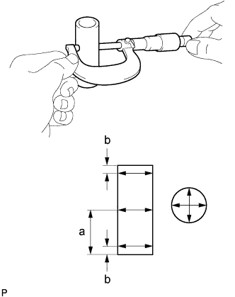
Inspect the main journals.
-
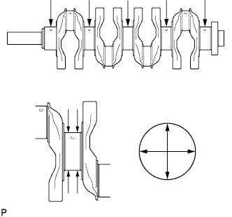
Using a micrometer, measure the diameter of each main journal.
Standard Journal Diameter Item Specified Condition No. 3 journal 59.981 to 59.994 mm (2.361 to 2.362 in.) Except No. 3 journal 59.987 to 60.000 mm (2.3617 to 2.3622 in.) If the diameter is not as specified, check the oil clearance. If necessary, replace the crankshaft.
-
Check each main journal for taper and out-of- round as shown in the illustration.
Maximum taper and out-of-round 0.005 mm (0.000197 in.) If the taper and out-of-round is more than the maximum, replace the crankshaft.
-
-
Inspect the crank pin.
-
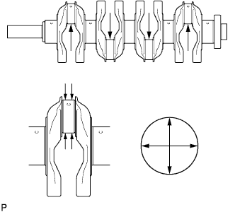
Using a micrometer, measure the diameter of each crank pin.
Standard diameter 52.989 to 53.002 mm (2.086 to 2.087 in.) If the diameter is not as specified, check the oil clearance. If necessary, replace the crankshaft.
-
Check each crank pin for taper and out-of-round as shown in the illustration.
Maximum taper and out-of-round 0.003 mm (0.000118 in.) If the taper and out-of-round is more than the maximum, replace the crankshaft.
-
-
-
INSPECT CRANKSHAFT OIL CLEARANCE
Tech Tips
-
Keep the lower bearings and crankshaft bearing caps together.
-
Arrange the thrust washers in the correct order.
-
Keep the upper crankshaft bearings and upper thrust washers together with the cylinder block.
-
Clean each main journal and bearing.
-
Check each main journal and bearing for pitting and scratches.
If the journal or bearing is damaged, replace the bearing.
-
Install the crankshaft bearings and upper crankshaft thrust washers.
-
Place the crankshaft on the cylinder block.
-
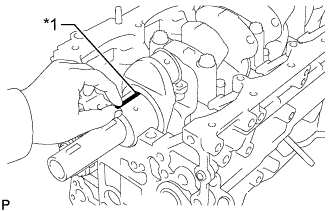
Text in Illustration *1 Plastigage Lay a strip of Plastigage across each journal.
-
Install the 5 crankshaft bearing caps with the 10 bolts Click here.
Note
Do not turn the crankshaft.
-
Remove the 10 bolts and 5 crankshaft bearing caps Click here.
-
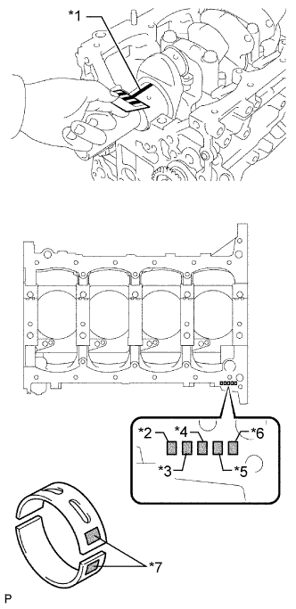
Text in Illustration *1 Plastigage *2 No. 1 Journal *3 No. 2 Journal *4 No. 3 Journal *5 No. 4 Journal *6 No. 5 Journal *7 Mark 1, 2 or 3 Measure the Plastigage at its widest point.
Standard Oil Clearance Item Specified Condition No. 3 journal 0.036 to 0.067 mm (0.00142 to 0.00264 in.) Other journals 0.030 to 0.061 mm (0.00118 to 0.00240 in.) Maximum oil clearance 0.10 mm (0.00394 in.) If the oil clearance is more than the maximum, replace the crankshaft bearing.
If replacing the cylinder block, measure the bearing standard clearance.
If replacing a bearing, first check the number on the cylinder block for the journal of the bearing. Then replace the bearing with one that has the same number. The standard thickness of each bearing is indicated by a 1, 2 or 3 mark on its surface.
Standard Cylinder Block Main Journal Bore Diameter Item Specified Condition Mark 1 64.004 to 64.010 mm (2.51984 to 2.52007 in.) Mark 2 64.011 to 64.016 mm (2.52011 to 2.52031 in.) Mark 3 64.017 to 64.022 mm (2.52035 to 2.52055 in.) Standard Bearing Center Wall Thickness Item Specified Condition Mark 1 1.987 to 1.990 mm (0.07823 to 0.07835 in.) Mark 2 1.991 to 1.993 mm (0.07839 to 0.07846 in.) Mark 3 1.994 to 1.996 mm (0.07850 to 0.07858 in.) -
Completely remove the Plastigage.
-
Perform the inspection above for each journal.
-
-
INSPECT NO. 1 BALANCE SHAFT
-
Inspect the diameter of the journal.
-
Using a micrometer, measure the diameter of the balance shaft main journals.
Standard Main Journal Diameter Item Specified Condition A 37.969 to 37.985 mm (1.49 to 1.50 in.) B 37.449 to 37.465 mm (1.474 to 1.475 in.)
-
-
Inspect the diameter of the bearing.
-
Using a cylinder gauge, measure the inside diameter of the balance shaft bearing.
Standard Bearing Inside Diameter Item Specified Condition A 38.025 to 38.045 mm (1.497 to 1.498 in.) B 37.525 to 37.545 mm (1.477 to 1.478 in.)
-
-
Inspect the oil clearance.
-
Subtract the balance shaft main journal diameter measurement from the balance shaft bearing inside diameter measurement.
Standard Oil Clearance Item Specified Condition A 0.040 to 0.076 mm (0.00157 to 0.00299 in.) B 0.060 to 0.096 mm (0.00236 to 0.00378 in.) Maximum oil clearance 0.15 mm (0.00591 in.) If the oil clearance is more than the maximum, replace the cylinder block and balance shaft.
-
-
-
INSPECT NO. 2 BALANCE SHAFT
-
Inspect the diameter of the journal.
-
Using a micrometer, measure the diameter of the balance shaft main journals.
Standard Main Journal Diameter Item Specified Condition A 37.969 to 37.985 mm (1.49 to 1.50 in.) B 37.449 to 37.465 mm (1.474 to 1.475 in.)
-
-
Inspect the diameter of the bearing.
-
Using a cylinder gauge, measure the inside diameter of the balance shaft bearing.
Standard Bearing Inside Diameter Item Specified Condition A 38.025 to 38.045 mm (1.497 to 1.498 in.) B 37.525 to 37.545 mm (1.477 to 1.478 in.)
-
-
Inspect the oil clearance.
-
Subtract the balance shaft main journal diameter measurement from the balance shaft bearing inside diameter measurement.
Standard Oil Clearance Item Specified Condition A 0.040 to 0.076 mm (0.00157 to 0.00299 in.) B 0.060 to 0.096 mm (0.00236 to 0.00378 in.) Maximum oil clearance 0.15 mm (0.00591 in.) If the oil clearance is more than the maximum, replace the cylinder block and balance shaft.
-
-
-
INSPECT NO. 1 OIL NOZZLE SUB-ASSEMBLY
-
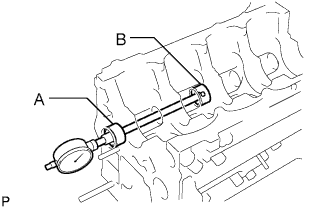
Push the check valve with a pin to check if it is stuck.
Text in Illustration Push If the check valve is stuck, replace the No. 1 oil nozzle.
-
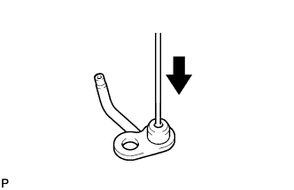
Push the check valve with a pin to check if it moves smoothly.
If the check valve does not move smoothly, clean or replace the No. 1 oil nozzle.
-
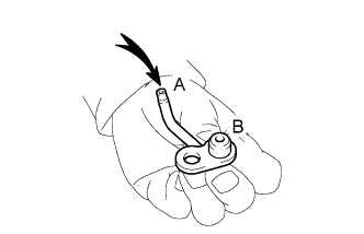
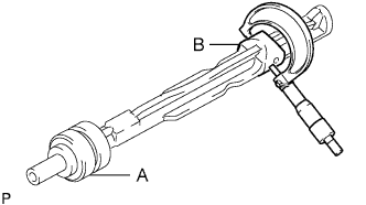
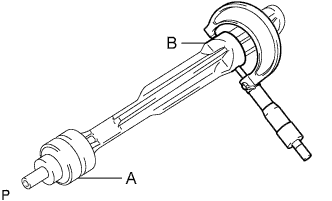
Apply air into A. Check that air does not leak through B.
Text in Illustration Air If air leaks, clean or replace the No. 1 oil nozzle.
-
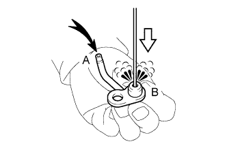
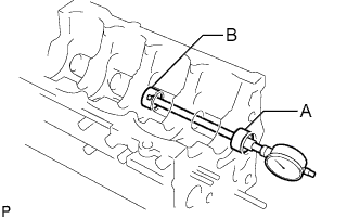
Push the check valve while applying air into A. Check that air passes through B.
Text in Illustration Air 
Push If air does not pass through B, clean or replace the No. 1 oil nozzle.
-
-
INSPECT CRANKSHAFT BEARING CAP SET BOLT
-
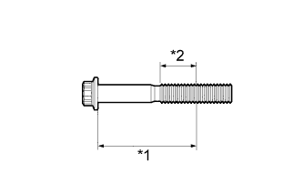
Text in Illustration *1 Distance *2 Measuring Area Using a vernier caliper, measure the diameter of the most elongated threads in the measuring area.
Distance 64 mm (2.52 in.) Standard diameter 10.76 to 10.97 mm (0.424 to 0.432 in.) Minimum diameter 10.66 mm (0.420 in.) If the diameter is less than the minimum, replace the crankshaft bearing cap bolt.
-
-
INSPECT CONNECTING ROD BOLT
-
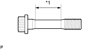
Text in Illustration *1 Tension Portion Using a vernier caliper, measure the tension portion diameter of the bolt.
Standard diameter 7.2 to 7.3 mm (0.283 to 0.287 in.) Minimum diameter 7.0 mm (0.276 in.) If the diameter is less than the minimum, replace the connecting rod bolt.
-