ENGINE UNIT INSPECTION

-
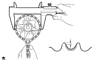
INSPECT CHAIN SUB-ASSEMBLY
-
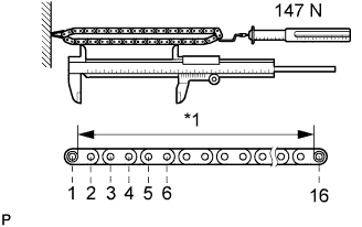
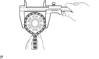
Text in Illustration *1 Measuring Area Pull the chain with a force of 147 N (15 kgf, 33.0 lbf) as shown in the illustration.
-
Using a vernier caliper, measure the length of 16 links.
Maximum chain elongation 147.5 mm (5.81 in.) If the elongation is more than the maximum, replace the chain.
Note
Perform the measurement at 3 random places.
-
-
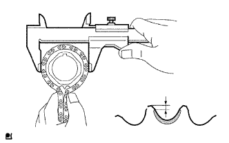
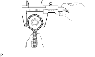
INSPECT NO. 2 CHAIN SUB-ASSEMBLY
-
Pull the chain with a force of 147 N (15 kgf, 33.0 lbf).
-
Using a vernier caliper, measure the length of 16 links.
Maximum chain elongation 123.6 mm (4.87 in.) If the elongation is more than the maximum, replace the chain.
Note
Perform the measurement at 3 random places.
-
-
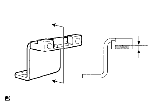
INSPECT NO. 1 CHAIN TENSIONER ASSEMBLY
-
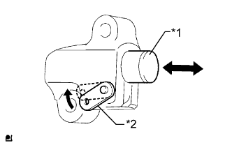
Text in Illustration *1 Plunger *2 Stopper Plate Move the stopper plate upward to release the lock. Push the plunger and check that it moves smoothly.
-
-
INSPECT NO. 2 CHAIN TENSIONER ASSEMBLY
-
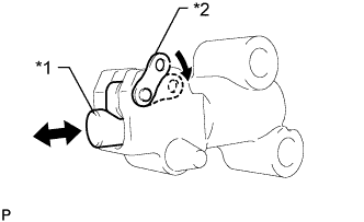
Text in Illustration *1 Plunger *2 Stopper Plate Move the stopper plate downward to release the lock. Push the plunger and check that it moves smoothly.
-
-
INSPECT CAMSHAFT TIMING SPROCKET
-
Measure the distance between the most worn out sprocket tip and the beginning of the worn area below the tip.
Minimum distance 1.0 mm (0.0394 in.) Text in Illustration 
Worn Area If the distance is less than the minimum, replace the sprocket.
If the worn area is too small or difficult to distinguish from a normal area, perform the following 2 steps.
-
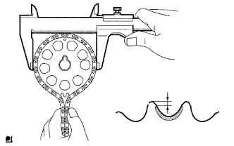
Wrap the chain around the sprocket.
-
Using a vernier caliper, measure the sprocket diameter with the chain.
Minimum sprocket diameter (with chain) 113.8 mm (4.48 in.) Tech Tips
The vernier caliper must contact the chain rollers for the measurement.
If the diameter is less than the minimum, replace the chain and sprocket.
-
-
INSPECT CAMSHAFT TIMING GEAR ASSEMBLY
-
Measure the distance between the most worn out timing gear tip and the beginning of the worn area below the tip.
Minimum distance 1.0 mm (0.0394 in.) Text in Illustration Worn Area If the distance is less than the minimum, replace the timing gear.
If the worn area is too small or difficult to distinguish from a normal area, perform the following 2 steps.
-
Wrap the chain around the timing gear.
-
Using a vernier caliper, measure the sprocket diameter with the chain.
Minimum sprocket diameter (with chain) 113.8 mm (4.48 in.) Tech Tips
The vernier caliper must contact the chain rollers for the measurement.
If the diameter is less than the minimum, replace the chain and timing gear.
-
-
INSPECT CRANKSHAFT TIMING GEAR
-
Measure the distance between the most worn out sprocket tip and the beginning of the worn area below the tip.
Minimum distance 1.0 mm (0.0394 in.) Text in Illustration Worn Area If the distance is less than the minimum, replace the sprocket.
If the worn area is too small or difficult to distinguish from a normal area, perform the following 2 steps.
-
Wrap the chain around the drive sprocket.
-
Using a vernier caliper, measure the sprocket diameter with the chain.
Minimum sprocket diameter (with chain) 59.4 mm (2.34 in.) Tech Tips
The vernier caliper must contact the chain rollers for the measurement.
If the diameter is less than the minimum, replace the chain and sprocket.
-
-
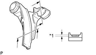
INSPECT CHAIN TENSIONER SLIPPER
-
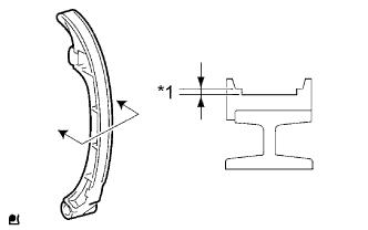
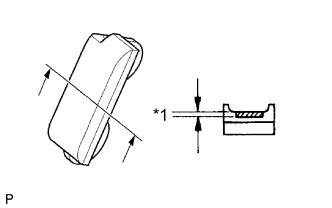
Text in Illustration *1 Wear Using a vernier caliper, measure the tensioner slipper wear.
Maximum wear 2.0 mm (0.0787 in.) If the wear is more than the maximum, replace the tensioner slipper.
-
-
INSPECT NO. 1 CHAIN VIBRATION DAMPER
-
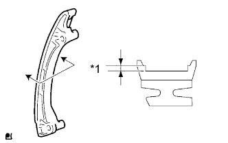
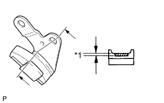
Text in Illustration *1 Wear Using a vernier caliper, measure the vibration damper wear.
Maximum wear 2.0 mm (0.0787 in.) If the wear is more than the maximum, replace the vibration damper.
-
-
INSPECT TIMING CHAIN GUIDE
-
Using a vernier caliper, measure the chain guide wear.
Maximum wear 0.5 mm (0.0197 in.) Text in Illustration Wear If the wear is more than the maximum, replace the timing chain guide.
-
-
INSPECT NO. 2 CRANKSHAFT TIMING SPROCKET
-
Wrap the chain around the sprocket.
-
Using a vernier caliper, measure the sprocket diameter with the chain.
Minimum sprocket diameter (with chain) 96.7 mm (3.81 in.) Tech Tips
The vernier caliper must contact the chain rollers for the measurement.
If the diameter is less than the minimum, replace the chain and sprocket.
-
-
INSPECT BALANCE SHAFT DRIVE GEAR SUB-ASSEMBLY
-
Wrap the chain around the sprocket.
-
Using a vernier caliper, measure the sprocket diameter with the chain.
Minimum sprocket diameter (with chain) 75.9 mm (2.99 in.) Tech Tips
The vernier caliper must contact the chain rollers for the measurement.
If the diameter is less than the minimum, replace the chain and sprocket.
-
-
INSPECT NO. 2 CHAIN VIBRATION DAMPER
-
Text in Illustration *1 Wear Using a vernier caliper, measure the vibration damper wear.
Maximum wear 1.0 mm (0.0394 in.) If the wear is more than the maximum, replace the vibration damper.
-
-
INSPECT NO. 3 CHAIN VIBRATION DAMPER
-
Text in Illustration *1 Wear Using a vernier caliper, measure the vibration damper wear.
Maximum wear 1.0 mm (0.0394 in.) If the wear is more than the maximum, replace the vibration damper.
-
-
INSPECT NO. 4 CHAIN VIBRATION DAMPER
-
Text in Illustration *1 Wear Using a vernier caliper, measure the vibration damper wear.
Maximum wear 1.0 mm (0.0394 in.) If the wear is more than the maximum, replace the vibration damper.
-
-
INSPECT CYLINDER HEAD SET BOLT
-
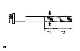
Text in Illustration *1 Measuring area *2 Distance Using a vernier caliper, measure the diameter of the most elongated threads in the measuring area.
Standard outside diameter 10.76 to 10.97 mm (0.424 to 0.432 in.) Minimum outside diameter 10.40 mm (0.409 in.) Distance 30 mm (1.18 in.) If a visual check reveals no excessively thin areas, check the center of the measuring area (see illustration) and find the area that has the smallest diameter.
If the diameter is less than the minimum, replace the cylinder head bolt.
-
-
INSPECT VALVE LASH ADJUSTER ASSEMBLY
Note
-
Keep the lash adjuster free from dirt and foreign objects.
-
Only use clean engine oil.
-
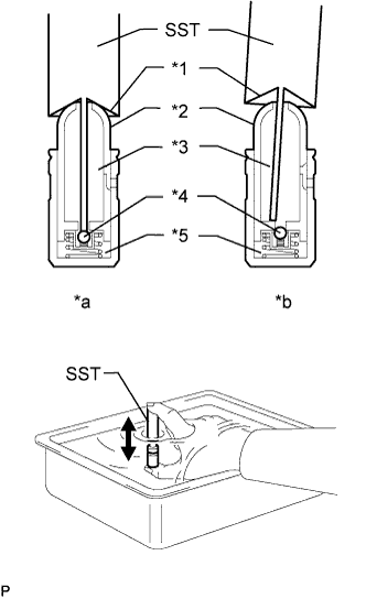
Text in Illustration *1 Taper Part *2 Plunger *3 Low Pressure Chamber *4 Check Ball *5 High Pressure Chamber *a CORRECT *b INCORRECT Place the lash adjuster into a container full of new engine oil.
-
Insert the tip of SST into the lash adjuster plunger and use the tip to press down on the check ball inside the plunger.
- SST
- 09276-75010
-
Squeeze SST and the lash adjuster together to move the plunger up and down 5 to 6 times.
-
Check the movement of the plunger and bleed air.
OK Plunger moves up and down. Note
When bleeding high-pressure air from the compression chamber, make sure that the tip of SST is actually pressing the check ball as shown in the illustration. If the check ball is not pressed, air will not bleed.
-
After bleeding the air, remove SST. Then try to quickly and firmly press the plunger with your fingers.
OK Plunger can be pressed 3 times. If the plunger can still be compressed after pressing it 3 times, replace the valve lash adjuster with a new one.
-
-
INSPECT CAMSHAFT
-
Check the camshaft runout.
-
Place the camshaft on V-blocks.
-
Using a dial indicator, measure the circle runout at the center journal.
Maximum circle runout 0.03 mm (0.00118 in.) If the circle runout is more than the maximum, replace the camshaft.
-
-
Using a micrometer, measure the cam lobe height.
Standard cam lobe height 42.855 to 42.955 mm (1.687 to 1.691 in.) Minimum cam lobe height 42.855 mm (1.687 in.) If the cam lobe height is less than the minimum, replace the camshaft.
-
Using a micrometer, measure the journal diameter.
Standard Journal Diameter Item Specified Condition No. 1 journal 35.949 to 35.965 mm (1.415 to 1.416 in.) Other journal 26.959 to 26.975 mm (1.061 to 1.062 in.) If the journal diameter is not as specified, check the oil clearance.
-
-
INSPECT NO. 2 CAMSHAFT
-
Check the camshaft runout.
-
Place the camshaft on V-blocks.
-
Using a dial indicator, measure the circle runout at the center journal.
Maximum circle runout 0.03 mm (0.00118 in.) If the circle runout is more than the maximum, replace the camshaft.
-
-
Using a micrometer, measure the cam lobe height.
Standard cam lobe height 42.854 to 42.954 mm (1.687 to 1.691 in.) Minimum cam lobe height 42.854 mm (1.687 in.) If the cam lobe height is less than the minimum, replace the camshaft.
-
Using a micrometer, measure the journal diameter.
Standard Journal Diameter Item Specified Condition No. 1 journal 35.949 to 35.965 mm (1.415 to 1.416 in.) Other journal 26.959 to 26.975 mm (1.061 to 1.062 in.) If the journal diameter is not as specified, check the oil clearance.
-
-
INSPECT CAMSHAFT THRUST CLEARANCE
-
Install the camshafts Click here.
-
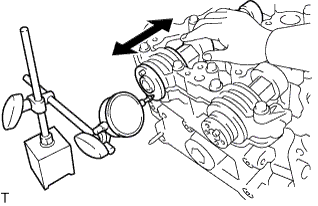
Using a dial indicator, measure the thrust clearance while moving the camshaft back and forth.
Standard thrust clearance 0.10 to 0.24 mm (0.00394 to 0.00945 in.) Maximum thrust clearance 0.26 mm (0.0102 in.) If the thrust clearance is more than the maximum, replace the cylinder head. If the thrust surface is damaged, replace the camshaft.
-
-
INSPECT CAMSHAFT OIL CLEARANCE
-
Clean the bearing caps and camshaft journals.
-
Place the camshafts on the cylinder head.
-
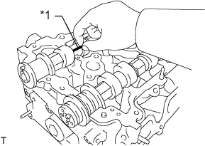
Text in Illustration *1 Plastigage Lay a strip of Plastigage across each of the camshaft journals.
-
Install the bearing caps Click here.
Note
Do not turn the camshafts.
-
Remove the bearing caps Click here.
-
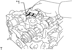
Text in Illustration *1 Plastigage Measure the Plastigage at its widest point.
Standard Oil Clearance Item Specified Condition No. 1 journal 0.035 to 0.072 mm (0.00138 to 0.00283 in.) Other journals 0.025 to 0.062 mm (0.000984 to 0.00244 in.) Maximum oil clearance 0.08 mm (0.00315 in.) If the oil clearance is more than the maximum, replace the camshaft. If necessary, replace the cylinder head sub-assembly.
-
Completely remove the Plastigage.
-
-
INSPECT EXHAUST MANIFOLD
-
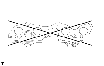
Using a precision straightedge and feeler gauge, measure the warpage of the surface that contacts the cylinder head.
Maximum warpage 0.7 mm (0.0276 in.) If the warpage is more than the maximum, replace the exhaust manifold.
-