CYLINDER HEAD GASKET INSTALLATION

-
INSTALL CYLINDER HEAD GASKET
-
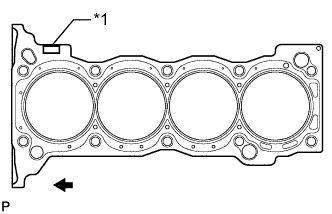
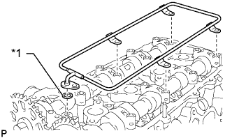
Text in Illustration *1 Lot No. 
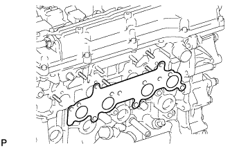
Front Place a new cylinder head gasket on the cylinder block surface with the lot No. stamp facing upward.
Note
Make sure that the cylinder head gasket is installed so that it is facing in the correct direction.
-
-
INSTALL CYLINDER HEAD SUB-ASSEMBLY
Tech Tips
The cylinder head bolts are tightened in 3 successive steps.
-
Place the cylinder head on the cylinder block.
Note
-
Make sure that no oil is on the mounting surface of the cylinder head.
-
Place the cylinder head on the cylinder block gently in order not to damage the gasket with the bottom part of the head.
-
-
Install the plate washers to the cylinder head bolts.
-
Apply a light coat of engine oil to the threads and under the heads of the cylinder head bolts.
-
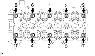
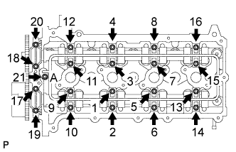
Step 1:
Using several steps, install and uniformly tighten the 10 cylinder head bolts with plate washers in the sequence shown in the illustration.
- Torque:
- 39 N*m { 398 kgf*cm, 29 ft.*lbf }
-
Mark the front of each cylinder head bolt head with paint.
-
Step 2:
Tighten the cylinder head bolts 90° in the sequence shown in step 1.
-
Step 3:
Tighten the cylinder head bolts another 90° in the sequence shown in step 1.
-
Check that the paint marks are now at a 180° angle to the front.
-
-
INSTALL VALVE STEM CAP
-
Apply a light coat of engine oil to the valve stem ends.
-
Install the 16 valve stem caps to the cylinder head.
Note
Do not drop the valve stem caps into the cylinder head.
-
-
INSTALL VALVE LASH ADJUSTER ASSEMBLY
-
Inspect each valve lash adjuster before installing it Click here.
-
Install the 16 valve lash adjusters to the cylinder head.
Note
Install each lash adjuster to the same place it was removed from.
-
-
INSTALL NO. 1 VALVE ROCKER ARM SUB-ASSEMBLY
-
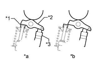
Text in Illustration *1 Valve Stem Cap *2 Valve Rocker Arm *3 Valve Lash Adjuster *a CORRECT *b INCORRECT Apply clean engine oil to the valve lash adjuster tips and valve stem cap surfaces.
-
Install the 16 valve rocker arms as shown in the illustration.
Note
Install each valve rocker arm to the same place it was removed from.
-
-
INSTALL CAMSHAFT
-
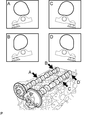
Apply clean engine oil to the camshaft cams and cylinder head journals.
-
Position the camshaft and No. 2 camshaft as shown in the illustration.
-
-
INSTALL CAMSHAFT BEARING CAP
-
Temporarily install the No. 1 camshaft bearing cap.
-
Check the proper location of each No. 2 camshaft bearing cap and install them.
-
Text in Illustration *1 O-Ring Install a new O-ring to the No. 1 camshaft bearing cap.
-
Temporarily install the oil delivery pipe.
-
Install the 21 bolts and tighten them in the order shown in the illustration.
- Torque:
- for bolt A
- 12 N*m { 122 kgf*cm, 9 ft.*lbf }
- except bolt A
- 16 N*m { 158 kgf*cm, 11 ft.*lbf }
-
-
INSTALL NO. 1 CHAIN VIBRATION DAMPER
-
Install the vibration damper with the bolt and nut.
- Torque:
- for bolt
- 21 N*m { 214 kgf*cm, 15 ft.*lbf }
- for nut
- 18 N*m { 184 kgf*cm, 13 ft.*lbf }
-
-
INSTALL CHAIN SUB-ASSEMBLY
-
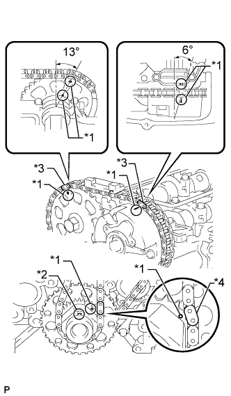
Text in Illustration *1 Timing Mark *2 Key *3 Mark Plate (Orange) *4 Mark Plate (Yellow) As shown in the illustration, install the chain to the sprocket and gear with the mark plates aligned with the timing marks on the sprocket and gear.
Tech Tips
-
The camshaft mark plate is orange.
-
The crankshaft mark plate is yellow.
-
-
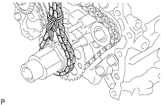
Use a rope to secure the chain of the crankshaft timing sprocket. Tie the rope near the sprocket.
Note
After the chain tensioner has been installed, the rope must be removed.
Tech Tips
The rope is used to prevent the chain from jumping a tooth.
-
-
INSTALL CHAIN TENSIONER SLIPPER
-
Install the tensioner slipper with the bolt.
- Torque:
- 21 N*m { 214 kgf*cm, 15 ft.*lbf }
-
-
INSTALL NO. 1 CHAIN TENSIONER ASSEMBLY
-
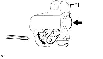
Text in Illustration *1 Plunger *2 Stopper Plate Move the stopper plate upward to release the lock and push the plunger deep into the tensioner.
-
Move the stopper plate downward to set the lock and insert a hexagon wrench into the hole of the stopper plate.
-
Install a new gasket and the chain tensioner with the bolt and nut.
- Torque:
- 10 N*m { 102 kgf*cm, 7 ft.*lbf }
-
-
INSTALL TIMING CHAIN GUIDE
-
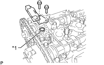
Text in Illustration *1 O-Ring Install a new O-ring to the camshaft bearing cap.
-
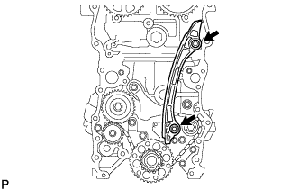
Install the timing chain guide with the 2 bolts.
- Torque:
- 10 N*m { 102 kgf*cm, 7 ft.*lbf }
-
-
INSTALL TIMING CHAIN COVER SUB-ASSEMBLY
-
Install the timing chain cover Click here.
-
-
INSTALL EXHAUST MANIFOLD
-
Install a new gasket.
-
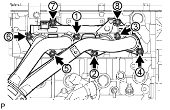
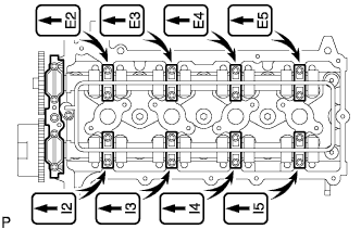
Install the exhaust manifold with 8 new nuts in the order shown in the illustration.
- Torque:
- 36 N*m { 367 kgf*cm, 27 ft.*lbf }
-
-
INSTALL AIR SWITCHING VALVE ASSEMBLY
-
Set the No. 1 exhaust manifold heat insulator in place.
-
Install the air switching valve with 2 new nuts.
- Torque:
- 20 N*m { 204 kgf*cm, 15 ft.*lbf }
-
Connect the connector.
-
w/ Manifold Absolute Pressure Sensor:
Connect the vacuum hose.
-
-
INSTALL NO. 4 INTAKE PIPE
-
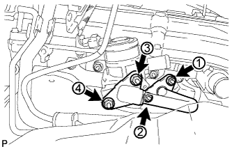
Install 2 new gaskets and the No. 4 intake pipe with 4 new nuts in the order shown in the illustration. Tighten the nuts labeled 1 and 3 to the torque specification again.
- Torque:
- 20 N*m { 204 kgf*cm, 15 ft.*lbf }
-
Check that the nuts are tightened to the torque specification.
-
-
INSTALL NO. 1 EXHAUST MANIFOLD HEAT INSULATOR
-
Install the No. 1 exhaust manifold heat insulator with the 5 bolts.
- Torque:
- 12 N*m { 122 kgf*cm, 9 ft.*lbf }
-
-
INSTALL ENGINE ASSEMBLY
-
Install the engine assembly Click here.
-