ENGINE UNIT INSTALLATION

-
INSTALL ENGINE OIL PRESSURE SWITCH ASSEMBLY
-
Clean the threads of the oil pressure switch and apply adhesive to them.
Adhesive Toyota Genuine Adhesive 1344, Three Bond 1344 or equivalent Note
Do not apply adhesive to the oil inlet port of the oil pressure switch.
-
Using a 24 mm deep socket wrench, install the oil pressure switch.
- Torque:
- 15 N*m { 150 kgf*cm, 11 ft.*lbf }
Note
Do not start the engine within 1 hour of installation.
-
-
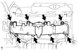
INSTALL OIL FILTER BRACKET SUB-ASSEMBLY
-
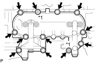
Text in Illustration *1 Nut Install a new gasket and the oil filter bracket with the 10 bolts and 2 nuts.
- Torque:
- 30 N*m { 301 kgf*cm, 22 ft.*lbf }
-
-
INSTALL EXHAUST MANIFOLD
-
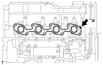
Text in Illustration *a Front Mark Install a new gasket to the cylinder head.
Tech Tips
Be sure to install a new gasket in the correct direction as shown in the illustration.
-
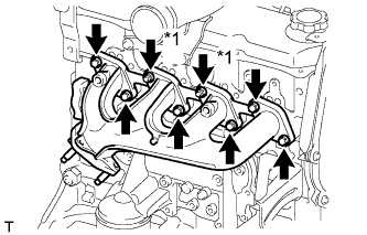
Text in Illustration *1 Nut Install the exhaust manifold with the 6 bolts and 2 new nuts. Uniformly tighten the bolts and nuts in several steps.
- Torque:
- 52 N*m { 530 kgf*cm, 38 ft.*lbf }
-
-
INSTALL NO. 1 EXHAUST MANIFOLD HEAT INSULATOR
-
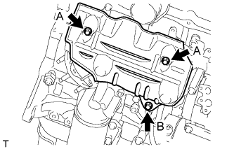
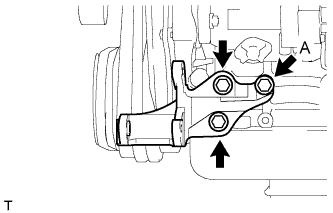
Install the insulator with the 3 bolts.
- Torque:
- for bolt A
- 18 N*m { 185 kgf*cm, 13 ft.*lbf }
- for bolt B
- 19 N*m { 195 kgf*cm, 14 ft.*lbf }
-
-
INSTALL VACUUM PUMP OIL OUTLET HOSE
-
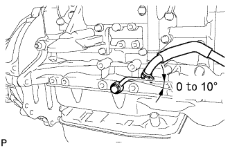
Install the vacuum pump oil outlet hose with the bolt and 2 new gaskets.
- Torque:
- 14 N*m { 140 kgf*cm, 10 ft.*lbf }
Tech Tips
The direction of the hose clamp is indicated in the illustration.
-
-
INSTALL UNION
-
Clean the threads of the union and apply adhesive to them.
Adhesive Toyota Genuine Adhesive 1344, Three Bond 1344 or equivalent -
Install the union to the cylinder block.
- Torque:
- 29 N*m { 290 kgf*cm, 21 ft.*lbf }
-
-
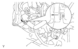
INSTALL VACUUM PUMP OIL INLET HOSE
-
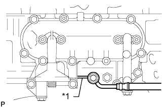
Connect the vacuum pump oil inlet hose with a new gasket and the union bolt.
- Torque:
- 14 N*m { 140 kgf*cm, 10 ft.*lbf }
Tech Tips
When tightening the inlet hose, hang the stopper-bar of the inlet hose on the filter bracket to prevent the inlet hose from rotating.
Text in Illustration *1 Stopper-bar
-
-
INSTALL NO. 1 FRONT ENGINE MOUNTING BRACKET RH
-
Install the engine mounting bracket with the 4 bolts.
- Torque:
- 49 N*m { 500 kgf*cm, 36 ft.*lbf }
-
-
INSTALL ENGINE OIL LEVEL DIPSTICK GUIDE
-
Apply a light coat of engine oil to a new O-ring.
-
Install the O-ring to the dipstick guide.
-
Install the dipstick guide with the 2 bolts.
- Torque:
- 18 N*m { 184 kgf*cm, 13 ft.*lbf }
-
Install the dipstick.
-
-
INSTALL NO. 1 FRONT ENGINE MOUNTING BRACKET LH
-
Install the engine mounting bracket with the 4 bolts.
- Torque:
- 49 N*m { 500 kgf*cm, 36 ft.*lbf }
-
-
INSTALL PUMP BRACKET
-
Install the pump bracket with the 3 bolts.
- Torque:
- for bolt A
- 57 N*m { 581 kgf*cm, 42 ft.*lbf }
- except bolt A
- 78 N*m { 795 kgf*cm, 58 ft.*lbf }
-
-
INSTALL NO. 1 GENERATOR BRACKET
-
Install the generator bracket with the 3 bolts.
- Torque:
- 49 N*m { 500 kgf*cm, 36 ft.*lbf }
-
-
INSTALL WATER BY-PASS HOSE UNION
-
Clean the threads of the water by-pass hose union and apply adhesive to them.
Adhesive Toyota Genuine Adhesive 1324, Three Bond 1324 or equivalent -
Install the water by-pass hose union.
- Torque:
- 39 N*m { 398 kgf*cm, 29 ft.*lbf }
-
-
INSTALL INTAKE MANIFOLD
-
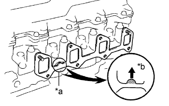
Text in Illustration *a Protrusion *b Upward Install a new gasket to the cylinder head with the protrusion facing upward.
-
Text in Illustration *1 Nut Install the intake manifold with the 6 bolts and 2 nuts. Uniformly tighten the bolts and nuts in several steps.
- Torque:
- 24 N*m { 240 kgf*cm, 17 ft.*lbf }
-
Install the wire harness bracket with the bolt.
- Torque:
- 13 N*m { 131 kgf*cm, 9 ft.*lbf }
-
-
INSTALL WATER OUTLET HOUSING
-
Install a new gasket to the cylinder head.
-
Install the outlet hosing with the 3 bolts
- Torque:
- 19 N*m { 194 kgf*cm, 14 ft.*lbf }
-
-
INSTALL ENGINE COOLANT TEMPERATURE SENSOR
-
Install a new gasket and the engine coolant temperature sensor with the bolt.
- Torque:
- 20 N*m { 200 kgf*cm, 14 ft.*lbf }
-
Connect the engine coolant temperature sensor connector.
-
-
INSTALL CRANKSHAFT POSITION SENSOR
-
Apply a light coat of engine oil to the O-ring of the crankshaft position sensor.
-
Install the crankshaft position sensor with the bolt.
- Torque:
- 5.0 N*m { 51 kgf*cm, 44 in.*lbf }
-
Connect the crankshaft position sensor connector.
-
-
INSTALL INJECTION PUMP ASSEMBLY
-
Temporarily install the injection pump to the timing gear case with the 2 nuts.
-
Temporarily install the injection pump stay to the injection pump rear end with the 3 bolts.
-
Rotate the pump body to align the marks on the pump flange and timing gear case.
-
Tighten the 2 nuts.
- Torque:
- 21 N*m { 209 kgf*cm, 15 ft.*lbf }
-
Tighten the 3 bolts.
- Torque:
- 26 N*m { 265 kgf*cm, 19 ft.*lbf }
-
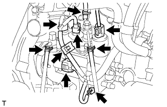
Connect the 3 fuel hoses.
-
Connect the 5 connectors and attach the wire harness clamp.
-
-
INSTALL INJECTION PUMP DRIVE PULLEY
-
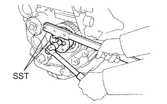
Using SST, install the injection pump drive pulley with the nut.
- SST
- 09213-14010 ( 91651-60865 )
- 09330-00021
- Torque:
- 64 N*m { 650 kgf*cm, 47 ft.*lbf }
-
-
INSTALL GLOW PLUG ASSEMBLY
-
Using a 12 mm deep socket wrench, install the 4 glow plugs.
- Torque:
- 13 N*m { 130 kgf*cm, 10 ft.*lbf }
-
-
INSTALL NOZZLE HOLDER & NOZZLE SET
-
Install 4 new injection nozzle seat gaskets and the 4 injection nozzle seats to the injection nozzle holes of the cylinder head.
-
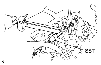
Using SST, install the 4 nozzle holder and nozzle sets.
- SST
- 09268-64010 ( 09268-64020 )
- Torque:
- 64 N*m { 650 kgf*cm, 47 ft.*lbf }
-
-
INSTALL NOZZLE LEAKAGE PIPE ASSEMBLY
-
Install 4 new ring packing washers and the leakage pipe with the 4 nuts.
- Torque:
- 30 N*m { 301 kgf*cm, 22 ft.*lbf }
-
Connect the fuel hose to the leakage pipe.
-
-
INSTALL NO. 1 GLOW PLUG CONNECTOR
-
Install the No. 1 glow plug resistor insulator and No. 1 glow plug connector.
-
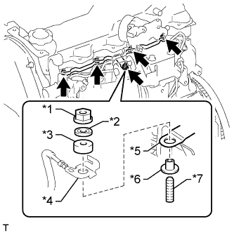
Text in Illustration *1 Nut *2 Washer *3 No. 2 Glow Plug Resistor Insulator *4 Engine Wire *5 No. 1 Glow Plug Connector *6 No. 1 Glow Plug Resistor Insulator *7 Bolt Install the glow plug connector with the 4 nuts. Uniformly tighten the nuts.
- Torque:
- 1.0 N*m { 10 kgf*cm, 9 in.*lbf }
-
Install the 4 screw grommets.
-
Connect the engine wire and install the No. 2 glow plug resistor insulator and washer with the bolt.
- Torque:
- 5.0 N*m { 51 kgf*cm, 44 in.*lbf }
-
-
INSTALL INJECTION PIPE SET
-
Install the 2 lower clamps to the intake manifold.
-
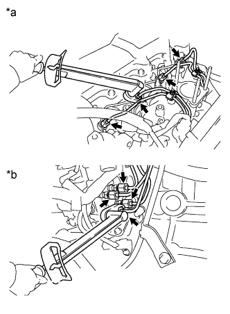
Text in Illustration *a for Injection Nozzle Side *b for Injection Pump Side Install the 4 injection pipes.
- Torque:
- 25 N*m { 250 kgf*cm, 18 ft.*lbf }
Note
Use the formula to calculate special torque values for situations where a union nut wrench is combined with a torque wrench Click here.
-
Install the 2 upper pipe clamps with the 2 nuts.
- Torque:
- 5.0 N*m { 51 kgf*cm, 44 in.*lbf }
-
-
INSTALL DIESEL THROTTLE BODY
-
Install a new gasket and the diesel throttle body.
-
Connect the throttle control motor connector.
-
Install the bracket with the 2 bolts.
- Torque:
- 13 N*m { 131 kgf*cm, 9 ft.*lbf }
-
Connect the throttle open switch connector.
-
-
INSTALL INTAKE FLANGE
-
Install a new gasket and the intake flange with the 3 nuts.
- Torque:
- 12 N*m { 122 kgf*cm, 9 ft.*lbf }
-
Connect the manifold absolute pressure sensor connector.
-
Install the heater hose bracket with the bolt.
- Torque:
- 14 N*m { 138 kgf*cm, 10 ft.*lbf }
-
Connect the PCV hose.
-
-
INSTALL CRANKSHAFT TIMING PULLEY
-
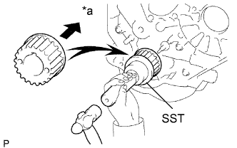
Text in Illustration *a Inside Align the key groove of the timing pulley with the pulley set key.
-
Using SST and a hammer, tap in the timing pulley with the flange side facing inward.
- SST
- 09223-46011
-
-
SET NO. 1 CYLINDER TO TDC/COMPRESSION
-
Text in Illustration *1 Timing Mark 
Turn Using the crankshaft pulley bolt, align the groove of the crankshaft pulley with the timing pointer by turning the crankshaft clockwise.
Note
Do not turn the crankshaft pulley counterclockwise.
-
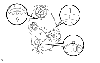
Set the timing and drive pulleys at each position.
Note
-
Make sure the engine is cold.
-
When turning the crankshaft or camshaft, the valve heads will hit against the piston top. Do not turn them more than necessary.
-
-
-
INSTALL TIMING BELT
Tech Tips
If reusing the timing belt, align the points marked during removal, and install the timing belt with the arrow pointing in the direction the belt moves when the engine is running.
-
Remove any oil or water on each pulley, and keep them clean.
-
Install the timing belt to the crankshaft timing and timing belt idlers.
-
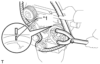
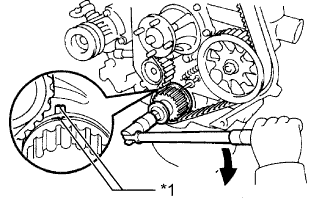
Text in Illustration *1 Timing Mark Using SST, slightly turn the injection pump drive pulley clockwise. Install the timing belt to the pulley, and align the timing marks of the drive pulley and timing belt case.
- SST
- 09960-10010 ( 09962-01000, 09963-01000 )
-
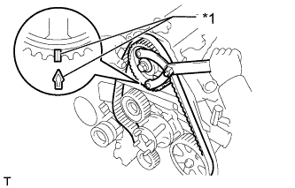
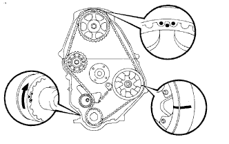
Text in Illustration *1 Timing Mark Using SST, slightly turn the camshaft timing pulley clockwise. Install the timing belt to the timing pulley, and align the timing marks of the timing pulley and timing belt case.
- SST
- 09960-10010 ( 09962-01000, 09963-01000 )
-
Check that the timing belt has tension between the injection pump drive and camshaft timing pulleys.
-
Install the timing belt to the No. 1 timing belt idler.
-
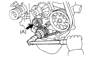
Loosen the No. 1 timing belt idler bolt (A), and stretch the timing belt.
-
Slowly turn the crankshaft pulley.
Note
Always turn the crankshaft clockwise.
-
Tighten the No. 1 timing belt idler bolt.
- Torque:
- 44 N*m { 449 kgf*cm, 33 ft.*lbf }
-
-
INSTALL TIMING BELT COVER
-
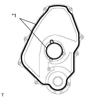
Text in Illustration *1 Gasket Install 2 new gaskets to the timing belt cover.
-
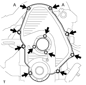
Install the timing belt cover with the 11 bolts and washers.
- Torque:
- for bolt A
- 8.5 N*m { 85 kgf*cm, 75 ft.*lbf }
- except bolt A
- 11 N*m { 107 kgf*cm, 8 ft.*lbf }
-
-
INSTALL CRANKSHAFT PULLEY
-
Align the key groove of the pulley with the pulley set key, and slide the pulley onto the crankshaft to install it.
-
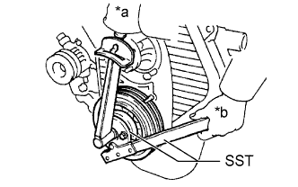
Text in Illustration *a Turn *b Hold Using SST, install the pulley bolt.
- SST
- 09213-54015 ( 91651-60855 )
- 09330-00021
- Torque:
- 235 N*m { 2396 kgf*cm, 173 ft.*lbf }
-
-
INSTALL NO. 1 COMPRESSOR MOUNTING BRACKET
-
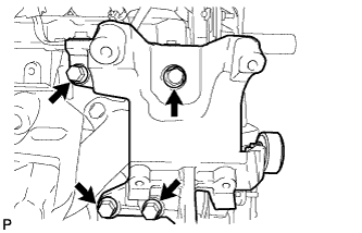
Install the No. 1 compressor mounting bracket with the 4 bolts.
- Torque:
- 81 N*m { 829 kgf*cm, 60 ft.*lbf }
-
-
INSTALL ENGINE WIRE