CYLINDER HEAD GASKET REMOVAL

-
REMOVE EXHAUST MANIFOLD
-
Remove the exhaust manifold Click here.
-
-
REMOVE TIMING BELT
-
Remove the timing belt Click here.
-
-
REMOVE DIESEL THROTTLE BODY
-
Remove the diesel throttle body Click here.
-
-
DISCONNECT COOLER COMPRESSOR ASSEMBLY
-
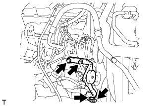
Remove the 4 bolts and idle pulley bracket.
-
Disconnect the connector.
-
Remove the 3 bolts and disconnect the cooler compressor.
Tech Tips
It is not necessary to completely remove the cooler compressor. With the hoses connected to the compressor, hang the compressor on the vehicle body with a rope.
-
-
REMOVE NO. 1 COMPRESSOR MOUNTING BRACKET
-
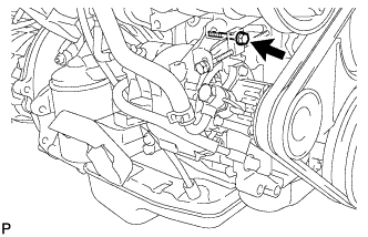
Remove the bolt and disconnect the generator.
-
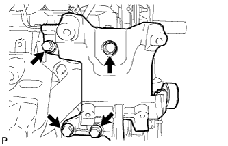
Remove the 4 bolts and No. 1 compressor mounting bracket.
-
-
DISCONNECT HEATER WATER HOSE SUB-ASSEMBLY
-
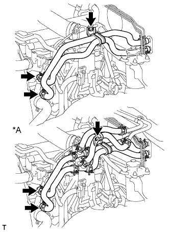
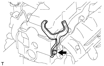
Text in Illustration *A for Rear Heater Remove the bolt and disconnect the heater water hoses.
-
-
REMOVE INJECTION PIPE SET
-
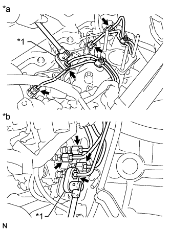
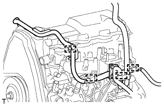
Text in Illustration *1 Union Nut Wrench *a for Injection Nozzle Side *b for Injection Pump Side Using a union nut wrench, loosen the 8 union nuts of the 4 injection pipes.
-
Remove the 2 nuts, 2 upper pipe clamps and 4 injection pipes with 2 lower pipe clamps.
-
-
DISCONNECT WIRE HARNESS
-
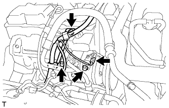
Remove the terminal cap.
-
Remove the nut and generator wire.
-
Disconnect the generator connector and cooler compressor connector.
-
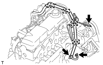
Detach the 4 wire harness clamps.
-
for RHD:
-
Detach the 5 wire harness clamps.
-
-
for LHD:
-
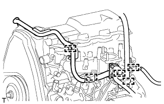
Detach the 4 wire harness clamps.
-
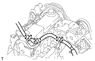
Detach the 3 wire harness clamps.
-
-
-
REMOVE WIRING HARNESS CLAMP BRACKET (for LHD)
-
Remove the bolt and wiring harness clamp bracket.
-
-
REMOVE CYLINDER HEAD COVER SUB-ASSEMBLY
-
Remove the 9 bolts, nut, cylinder head cover and gasket.
-
-
REMOVE CAMSHAFT
-
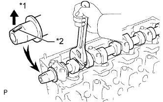
Text in Illustration *1 Upward *2 Key Groove Turn the camshaft with a wrench so that the key groove faces upward.
-
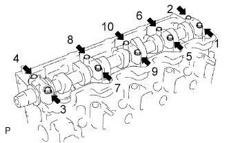
Uniformly loosen and remove the 10 bearing cap bolts in several steps in the sequence shown in the illustration.
-
Remove the 5 bearing caps and camshaft.
Tech Tips
Arrange the bearing caps in the correct order.
-
-
REMOVE CYLINDER HEAD SUB-ASSEMBLY
-
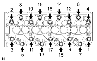
Uniformly loosen and remove the 18 cylinder head bolts in several steps in the sequence shown.
Note
Head warpage or cracking could result from removing bolts in an incorrect order.
-
Lift the cylinder head from the dowels on the cylinder block to remove it, and place the cylinder head on wooden blocks on a workbench.
Note
Do not damage the contact surfaces of the cylinder head and cylinder block.
Tech Tips
If the cylinder head is difficult to lift off, pry between the cylinder head and block with a screwdriver.
-
-
INSPECT CYLINDER HEAD SET BOLT
-
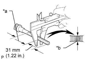
Text in Illustration *a Measuring Point *b Elongated Thread Using a vernier caliper, measure the minimum outer diameter of the elongated thread at the measuring point.
Standard outer diameter 11.80 to 12.00 mm (0.465 to 0.472 in.) Minimum outer diameter 11.60 mm (0.457 in.) If the diameter is less than the minimum, replace the cylinder head set bolt.
-
-
REMOVE CYLINDER HEAD GASKET