CAMSHAFT INSTALLATION

-
INSTALL CAMSHAFT
-
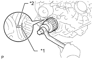
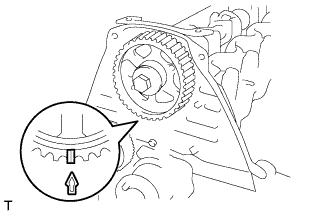
Text in Illustration *1 Timing Mark *2 Protrusion Check that the timing mark of the crankshaft timing pulley is in the position shown in the illustration.
-
Install the camshaft.
-
Place the camshaft on the cylinder head with the key groove facing upward.
-
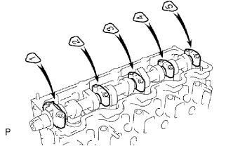
Install the 5 bearing caps in their proper locations.
-
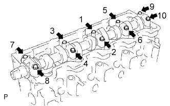
Apply a light coat of engine oil to the threads and under the heads of the bearing cap bolts.
-
Install and uniformly tighten the 10 bearing cap bolts in several steps in the sequence shown in the illustration.
- Torque:
- 25 N*m { 255 kgf*cm, 18 ft.*lbf }
-
-
-
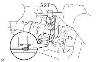
INSTALL CAMSHAFT OIL SEAL
-
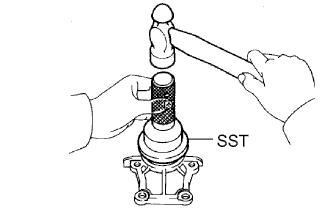
Using SST and a hammer, tap in a new oil seal until its surface is flush with the oil seal retainer edge.
- SST
- 09960-10010 ( 09962-01000, 09963-01000 )
-
Apply MP grease to the lip of the oil seal.
-
-
INSTALL CAMSHAFT OIL SEAL RETAINER
-
Install a new gasket and the retainer with the 4 bolts.
- Torque:
- 18 N*m { 184 kgf*cm, 13 ft.*lbf }
-
-
INSTALL NO. 2 TIMING BELT COVER
-
Install the timing belt cover with the 4 bolts.
- Torque:
- 18 N*m { 184 kgf*cm, 13 ft.*lbf }
-
-
INSTALL CAMSHAFT TIMING PULLEY
-
Install the woodruff key to the key groove of the camshaft.
-
Align the timing mark on the camshaft timing pulley with the timing mark on the No. 2 timing belt cover and temporarily install the pulley with the bolt.
-
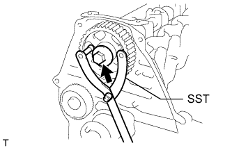
Using SST, tighten the bolt.
- SST
- 09960-10010 ( 09962-01000, 09963-01000 )
- Torque:
- 98 N*m { 999 kgf*cm, 72 ft.*lbf }
-
-
SET NO. 1 CYLINDER TO TDC/COMPRESSION
-
Text in Illustration *1 Timing Mark 
Turn Using the crankshaft pulley bolt, align the groove of the crankshaft pulley with the timing pointer by turning the crankshaft clockwise.
Note
Do not turn the crankshaft pulley counterclockwise.
-
Set the timing and drive pulleys at each position.
Note
-
Make sure the engine is cold.
-
When turning the crankshaft or camshaft, the valve heads will hit against the piston top. Do not turn them more than necessary.
-
-
-
INSTALL TIMING BELT
Tech Tips
If reusing the timing belt, align the points marked during removal, and install the timing belt with the arrow pointing in the direction the belt moves when the engine is running.
-
Remove any oil or water on each pulley, and keep them clean.
-
Install the timing belt to the crankshaft timing and timing belt idlers.
-
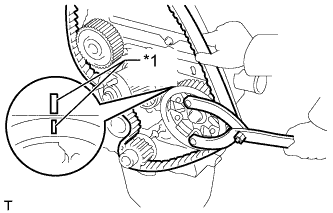
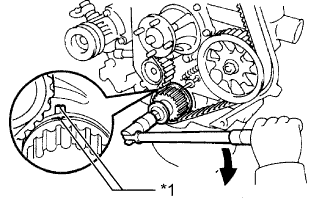
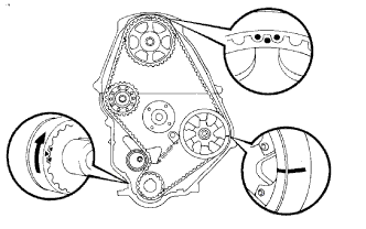
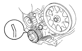
Text in Illustration *1 Timing Mark Using SST, slightly turn the injection pump drive pulley clockwise. Install the timing belt to the pulley, and align the timing marks of the drive pulley and timing belt case.
- SST
- 09960-10010 ( 09962-01000, 09963-01000 )
-
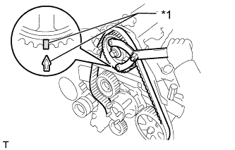
Text in Illustration *1 Timing Mark Using SST, slightly turn the camshaft timing pulley clockwise. Install the timing belt to the timing pulley, and align the timing marks of the timing pulley and timing belt case.
- SST
- 09960-10010 ( 09962-01000, 09963-01000 )
-
Check that the timing belt has tension between the injection pump drive and camshaft timing pulleys.
-
Install the timing belt to the No. 1 timing belt idler.
-
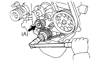
Loosen the No. 1 timing belt idler bolt (A), and stretch the timing belt.
-
Slowly turn the crankshaft pulley.
Note
Always turn the crankshaft clockwise.
-
Tighten the No. 1 timing belt idler bolt.
- Torque:
- 44 N*m { 449 kgf*cm, 33 ft.*lbf }
-
-
CHECK NO. 1 CYLINDER TO TDC/COMPRESSION
-
Slowly turn the crankshaft pulley 2 revolutions from TDC to TDC.
Note
Always turn the crankshaft clockwise.
-
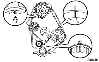
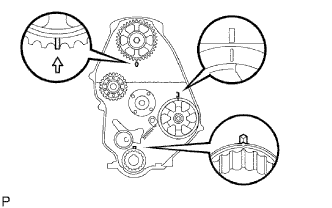
Check that the timing marks for each pulley align as shown in the illustration.
If the timing marks do not align, remove the timing belt and reinstall it.
-
-
INSTALL TIMING BELT GUIDE
-
Install the timing belt guide with the cup side facing outward.
-
-
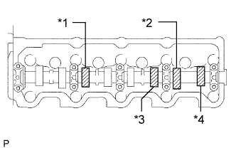
INSPECT VALVE CLEARANCE
-
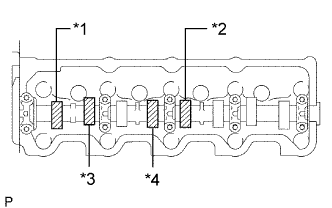
Text in Illustration *1 No. 1 EX *2 No. 3 EX *3 No. 1 IN *4 No. 2 IN Check only the valves indicated in the illustration.
-
Using a feeler gauge, measure the clearance between the valve lifter and camshaft.
Standard Valve Clearance (Cold) Item Specified Condition Intake 0.20 to 0.30 mm (0.00787 to 0.0118 in.) Exhaust 0.40 to 0.50 mm (0.0158 to 0.0197 in.) -
Record the out-of-specification valve clearance measurements. They will be used later to determine the required replacement adjusting shim.
-
-
Turn the crankshaft 1 revolution (360°) and align the mark as above.
-
Text in Illustration *1 No. 2 EX *2 No. 4 EX *3 No. 3 IN *4 No. 4 IN Check only the valves indicated in the illustration.
-
Using a feeler gauge, measure the clearance between the valve lifter and camshaft.
Standard Valve Clearance (Cold) Item Specified Condition Intake 0.20 to 0.30 mm (0.00787 to 0.0118 in.) Exhaust 0.40 to 0.50 mm (0.0158 to 0.0197 in.) -
Record the out-of-specification valve clearance measurements. They will be used later to determine the required replacement adjusting shim.
-
-
-
ADJUST VALVE CLEARANCE
-
Remove the adjusting shim.
-
Turn the crankshaft so that the cam lobe of the camshaft on the valve being adjusted points upward.
-
Using SST, press down the valve lifter.
- SST
- 09248-64011
-
Position the notch of the valve lifter so that it faces the exhaust manifold side.
-
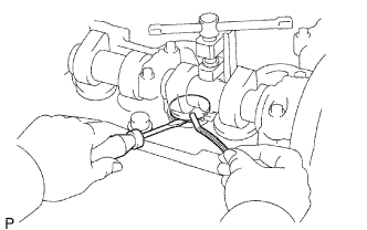
Remove the adjusting shim with a screwdriver and magnet hand.
-
-
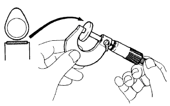
Determine the replacement adjusting shim size according to the formula and charts below.
-
Using a micrometer, measure the thickness of the removed shim.
-
Calculate the thickness of a new shim so that the valve clearance comes within the specified value.
T = Thickness of removed shim
A = Measured valve clearance
N = Thickness of new shim
Intake N = T + (A - 0.25 mm (0.00984 in.)) Exhaust N = T + (A - 0.45 mm (0.0177 in.)) -
Select a new shim with a thickness as close as possible to the calculated value.
Tech Tips
Shims are available in 17 sizes in increments of 0.05 mm (0.00197 in.), from 2.50 mm (0.0984 in.) to 3.30 mm (0.130 in.).
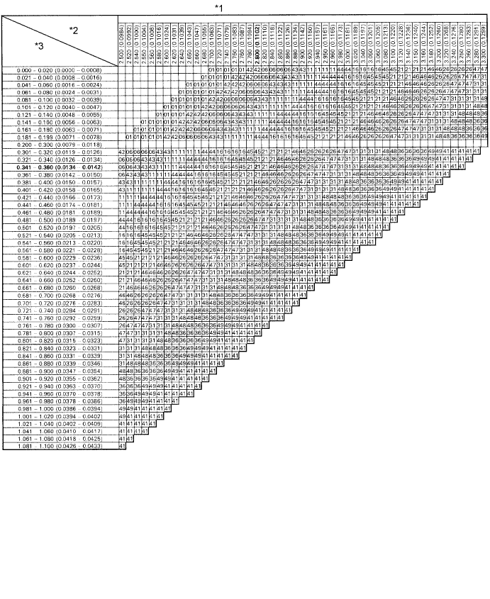
Text in Illustration *1 Adjusting Shim Selection Chart (Intake) *2 Removed shim thickness mm (in.) *3 Measure clearance mm (in.) - - New Shim Thickness mm (in.) Shim No. Thickness Shim No. Thickness 01 2.50 (0.0984) 46 2.95 (0.116) 42 2.55 (0.100) 26 3.00 (0.118) 06 2.60 (0.102) 47 3.05 (0.120) 43 2.65 (0.104) 31 3.10 (0.122) 11 2.70 (0.106) 48 3.15 (0.124) 44 2.75 (0.108) 36 3.20 (0.126) 16 2.80 (0.110) 49 3.25 (0.128) 45 2.85 (0.112) 41 3.30 (0.130) 21 2.90 (0.114) Intake valve clearance (Cold) 0.20 to 0.30 mm (0.00787 to 0.0118 in.) EXAMPLE:
A 2.80 mm (0.110 in.) shim is installed and the measured clearance is 0.350 mm (0.0138 in.). Replace the 2.80 mm (0.110 in.) shim with a No. 21 shim.
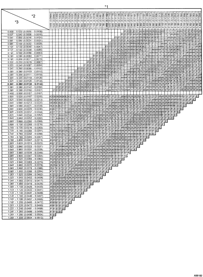
Text in Illustration *1 Adjusting Shim Selection Chart (Exhaust) *2 Removed Shim Thickness mm (in.) *3 Measure Clearance mm (in.) - - New Shim Thickness mm (in.) Shim No. Thickness Shim No. Thickness 01 2.50 (0.0984) 46 2.95 (0.116) 42 2.55 (0.100) 26 3.00 (0.118) 06 2.60 (0.102) 47 3.05 (0.120) 43 2.65 (0.104) 31 3.10 (0.122) 11 2.70 (0.106) 48 3.15 (0.124) 44 2.75 (0.108) 36 3.20 (0.126) 16 2.80 (0.110) 49 3.25 (0.128) 45 2.85 (0.112) 41 3.30 (0.130) 21 2.90 (0.114) Exhaust valve clearance (Cold) 0.40 to 0.50 mm (0.0157 to 0.0196 in.) EXAMPLE:
A 2.80 mm (0.110 in.) shim is installed and the measured clearance is 0.350 mm (0.0138 in.). Replace the 2.80 mm (0.110 in.) shim with a No. 11 shim.
-
-
Install a new adjusting shim.
-
Install a new adjusting shim to the valve lifter.
-
Remove SST.
-
-
Recheck valve clearance.
-
-
INSTALL CYLINDER HEAD COVER SUB-ASSEMBLY
-
Remove any old packing (FIPG material).
-
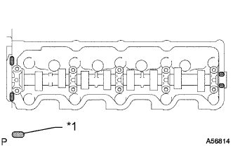
Text in Illustration *1 Seal Packing Apply seal packing to the cylinder head as shown in the illustration.
Seal packing Toyota Genuine Seal Packing Black, Three Bond 1207B or equivalent -
Install the gasket to the cylinder head cover.
-
Install the cylinder head cover with the 9 bolts and nut. Uniformly tighten the bolts and nut in several steps.
- Torque:
- 12 N*m { 122 kgf*cm, 9 ft.*lbf }
-
-
INSTALL INTAKE PIPE
-
Install the intake pipe with the 2 bolts.
- Torque:
- 18 N*m { 184 kgf*cm, 13 ft.*lbf }
-
Tighten the intake pipe clamp.
- Torque:
- 6.0 N*m { 61 kgf*cm, 53 in.*lbf }
-
-
INSTALL TIMING BELT COVER
-
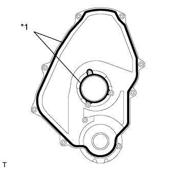
Text in Illustration *1 Gasket Install 2 new gaskets to the timing belt cover.
-
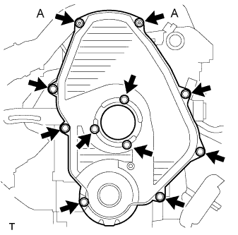
Install the timing belt cover with the 11 bolts and washers.
- Torque:
- for bolt A
- 8.5 N*m { 85 kgf*cm, 75 ft.*lbf }
- except bolt A
- 11 N*m { 107 kgf*cm, 8 ft.*lbf }
-
-
INSTALL IDLE PULLEY ASSEMBLY
-
Install the idle pulley bracket with the 2 bolts.
- Torque:
- 29 N*m { 300 kgf*cm, 22 ft.*lbf }
-
-
INSTALL CRANKSHAFT PULLEY
-
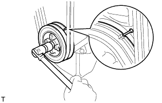
Align the key groove of the pulley with the pulley set key, and slide the pulley onto the crankshaft to install it.
-
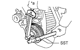
Text in Illustration *a Turn *b Hold Using SST, install the pulley bolt.
- SST
- 09213-54015 ( 91651-60855 )
- 09330-00021
- Torque:
- 235 N*m { 2396 kgf*cm, 173 ft.*lbf }
-
-
INSTALL VANE PUMP DRIVE PULLEY
-
Install the vane pump drive pulley and cooler compressor drive pulley with the 4 bolts.
- Torque:
- 19 N*m { 194 kgf*cm, 14 ft.*lbf }
-
-
INSTALL FAN SHROUD
-
Install the fan pulley to the water pump.
-
Install the shroud together with the coupling fan between the radiator and engine.
Note
Be careful not to damage the radiator core.
-
Temporarily install the fluid coupling fan to the fan pulley with the 4 nuts. Tighten the nuts as much as possible by hand.
-
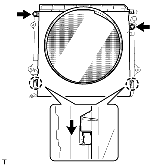
Attach the claws of the shroud as shown in the illustration.
-
Install the shroud with the 2 bolts.
- Torque:
- 5.0 N*m { 51 kgf*cm, 44 in.*lbf }
-
Install the fan and generator V belt and vane pump V belt Click here.
-
Tighten the 4 nuts of the fluid coupling fan.
- Torque:
- 19 N*m { 189 kgf*cm, 14 ft.*lbf }
-
-
INSTALL RADIATOR RESERVE TANK ASSEMBLY
-
Install the radiator reservoir with the 3 bolts.
- Torque:
- 5.0 N*m { 51 kgf*cm, 44 in.*lbf }
-
Connect the radiator reservoir hose to the radiator tank side.
-
-
INSTALL NO. 1 RADIATOR HOSE
-
Install the hose clamp with the 2 nuts.
- Torque:
- 8.5 N*m { 87 kgf*cm, 75 in.*lbf }
-

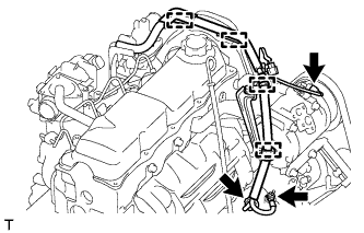
Text in Illustration *a Upper *b RH Side Install the radiator hose.
Tech Tips
Position the hose clamps as shown in the illustration.
-
-
INSTALL WIRING HARNESS CLAMP BRACKET (for LHD)
-
Install the wiring harness clamp bracket with the bolt.
- Torque:
- 22 N*m { 219 kgf*cm, 16 ft.*lbf }
-
-
CONNECT WIRE HARNESS
-
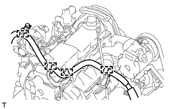
Attach the 4 wire harness clamps.
-
Install the generator wire with the nut.
- Torque:
- 9.8 N*m { 100 kgf*cm, 87 in.*lbf }
-
Install the terminal cap.
-
Connect the generator connector and cooler compressor connector.
-
for LHD:
Attach the 4 wire harness clamps.
-
-
INSTALL AIR CLEANER CASE ASSEMBLY
-
Install the air cleaner case with the 3 bolts.
- Torque:
- 12 N*m { 122 kgf*cm, 9 ft.*lbf }
-
-
INSTALL AIR CLEANER FILTER ELEMENT SUB-ASSEMBLY
-
INSTALL RESONATOR WITH AIR CLEANER CAP SUB-ASSEMBLY
-
Insert the hinge part of the air cleaner cap and hose into the air cleaner case, and then attach the 4 hook clamps.
-
Connect the air cleaner cap sub-assembly with the clamp.
- Torque:
- 5.0 N*m { 51 kgf*cm, 44 in.*lbf }
-
Attach the wire harness clamp.
-
Connect the 2 clamps and connector.
-
-
INSTALL FRONT FENDER APRON SEAL RH
-
Install the front fender apron seal with the 4 clips.
-
-
ADD ENGINE COOLANT
-
Tighten the radiator drain cock plug by hand.
-
Tighten the cylinder block drain cock plug.
- Torque:
- 13 N*m { 130 kgf*cm, 9 ft.*lbf }
-
Slowly fill the system with engine coolant.
Standard capacity 8.6 liters (9.0 US qts, 7.6 Imp. qts) Note
Do not substitute plain water for engine coolant.
Tech Tips
-
Use only Toyota Super Long Life Coolant or similar high quality ethylene glycol based non-silicate, non-amine, non-nitrite, and non-borate coolant with long-life hybrid organic acid technology (coolant with long-life hybrid organic acid technology consists of a combination of low phosphates and organic acids.)
-
New Toyota vehicles are filled with Toyota Super Long Life Coolant. When replacing the coolant, Toyota Super Long Life Coolant (color is pink, premixed ethylene glycol concentration is approximately 50% and freezing temperature is -35°C (-31°F)) is recommended
-
-
Slowly pour coolant into the radiator reservoir until it reaches the Full line.
-
Install the reservoir cap.
-
Press the No. 1 and No. 2 radiator hoses several times by hand, and then check the coolant level. If the coolant level is low, add coolant.
-
Install the radiator cap.
-
Start the engine and warm it up until the thermostat opens.
Tech Tips
The thermostat opening timing can be confirmed by pressing the No. 2 radiator hose by hand and checking when the engine coolant starts to flow inside the hose.
-
Maintain the engine speed at 2000 to 2500 rpm.
Note
-
Make sure that the radiator reservoir still has some coolant in it.
-
Pay attention to the needle of the water temperature meter. Make sure that the needle does not show an abnormally high temperature.
-
If there is not enough coolant, the engine may burn out or overheat.
-
Immediately after starting the engine, if the radiator reservoir does not have any coolant, perform the following: 1) stop the engine, 2) wait until the coolant has cooled down, and 3) add coolant until the coolant is filled to the F line.
-
Run the engine at 2000 rpm until the coolant level has stabilized.
-
-
Press the No. 1 and No. 2 radiator hoses several times by hand to bleed air.
CAUTION:
-
Wear protective gloves. Heat areas on the parts may injure your hands.
-
Be careful as the radiator hoses are hot.
-
Keep your hands away from the fan.
-
-
Stop the engine, and wait until the engine coolant cools down to ambient temperature.
CAUTION:
Do not remove the radiator cap while the engine and radiator are still hot. Pressurized, hot engine coolant and steam may be released and cause serious burns.
-
Check that the coolant level is between the Full and Low lines.
If the coolant level is below the Low line, repeat all of the steps above.
If the coolant level is above the Full line, drain coolant so that the coolant level is between the Full and Low lines.
-
-
CONNECT CABLE TO NEGATIVE BATTERY TERMINAL
Note
When disconnecting the cable, some systems need to be initialized after the cable is reconnected Click here.
-
INSPECT FOR ENGINE COOLANT LEAK
CAUTION:
To avoid being burned, do not remove the radiator reservoir cap while the engine and radiator are still hot. Thermal expansion may cause hot engine coolant and steam to blow out from the radiator.
-
Fill the radiator with coolant and attach a radiator cap tester to the radiator.
-
Warm up the engine.
-
Using a radiator cap tester, increase the pressure inside the radiator to 123 kPa (1.3 kgf/cm2, 18 psi), and check that the pressure does not drop.
If the pressure drops, check the hoses, radiator or water pump for leaks. If no external leaks are found, check the heater core, cylinder block, and cylinder head.
-
-
INSPECT ENGINE IDLE SPEED
-
Warm up the engine.
-
When using the intelligent tester:
-
Connect the intelligent tester to the DLC3.
Idle speed 720 to 820 rpm Note
-
Turn all the electrical systems and the A/C off.
-
When checking the idling speed, the shift lever should be in neutral.
Tech Tips
Refer to the intelligent tester operator's manual for further details.
-
-
-
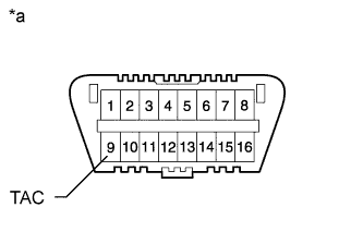
Text in Illustration *a Front View of DLC3 When not using an intelligent tester:
-
Using SST, connect the tachometer test probe to terminal 9 (TAC) of the DLC3.
- SST
- 09843-18040
-
Check the idle speed.
Standard idle speed 720 to 820 rpm Note
-
Turn all the electrical systems and the A/C off.
-
When checking the idling speed, the shift lever should be in neutral.
-
Confirm the terminal number before connecting them. Connecting the wrong terminal can be damage the engine.
-
-
-
-
INSPECT MAXIMUM ENGINE SPEED
-
Start the engine.
-
Fully depress the accelerator pedal.
-
Check the maximum speed.
Maximum engine speed 4850 to 4950 rpm
-
-
INSTALL NO. 1 ENGINE UNDER COVER SUB-ASSEMBLY
-
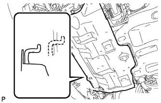
Hook the engine under cover to the vehicle body as shown in the illustration.
-
Install the 4 bolts.
- Torque:
- 29 N*m { 296 kgf*cm, 21 ft.*lbf }
-
-
INSTALL FRONT BUMPER COVER LOWER
-
Install the front bumper cover lower with the 5 bolts and clip.
- Torque:
- 8.0 N*m { 82 kgf*cm, 71 in.*lbf }
-
-
INSTALL UPPER RADIATOR SUPPORT SEAL
-
Install the upper radiator support seal with the 13 clips.
-