ENGINE ASSEMBLY INSTALLATION

-
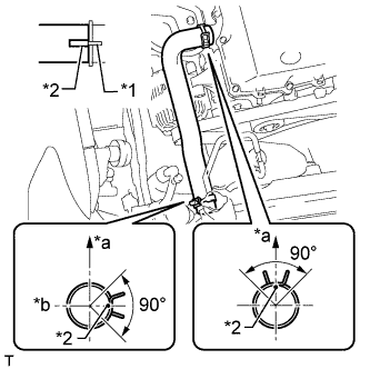
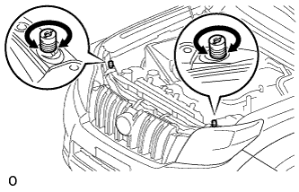
INSTALL NO. 1 ENGINE HANGER
-
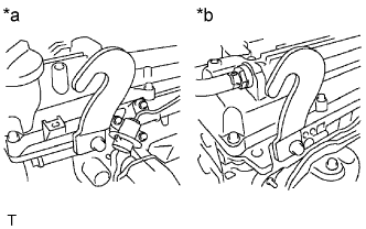
Text in Illustration *a LH Side *b RH Side Install 2 engine hangers with 2 bolts as shown in the illustration.
- Torque:
- 42 N*m { 428 kgf*cm, 31 ft.*lbf }
Tech Tips
No. 1 Engine Hanger 12281-75040 Bolt 91552-A1020
-
-
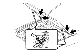
REMOVE ENGINE FROM ENGINE STAND
-
Attach an engine sling device and hang the engine with a chain block.
Note
Pay attention to the angle of the sling device as the engine assembly or No. 1 engine hanger may be damaged or deformed if the angle is incorrect.
-
Lift the engine and remove it from the engine stand.
-
-
INSTALL ENGINE ASSEMBLY
-
Slowly lower the engine into the engine compartment.
-
Install the engine with the 4 bolts and 4 nuts.
- Torque:
- 40 N*m { 408 kgf*cm, 30 ft.*lbf }
-
Remove the 2 bolts and 2 engine hangers.
-
-
INSTALL REAR END PLATE
-
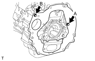
Install the rear end plate with the 2 bolts.
- Torque:
- for bolt A
- 18 N*m { 184 kgf*cm, 13 ft.*lbf }
- for bolt B
- 18 N*m { 178 kgf*cm, 13 ft.*lbf }
-
Attach the flywheel housing dust seal.
-
-
INSTALL FLYWHEEL SUB-ASSEMBLY (for Manual Transmission)
-
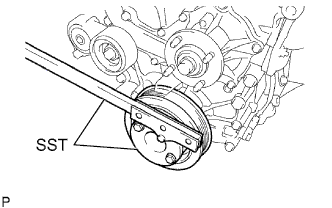
Using SST, hold the crankshaft.
- SST
- 09213-54015 ( 91651-60855 )
- 09330-00021
-
Clean the bolts and bolt holes.
-
Apply adhesive to 2 or 3 threads at the end of each of the 10 bolts.
Adhesive Toyota Genuine Adhesive 1324, Three Bond 1324 or equivalent -
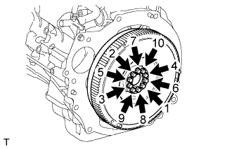
Install and uniformly tighten the 10 bolts in several steps in the sequence shown in the illustration.
- Torque:
- 27 N*m { 270 kgf*cm, 20 ft.*lbf }
-
Mark the top of the bolts with paint.
-
Tighten the 10 bolts 90° in the same sequence.
-
Check that the paint marks are now at a 90° angle to the top.
-
-
INSTALL CLUTCH DISC ASSEMBLY (for Manual Transmission)
-
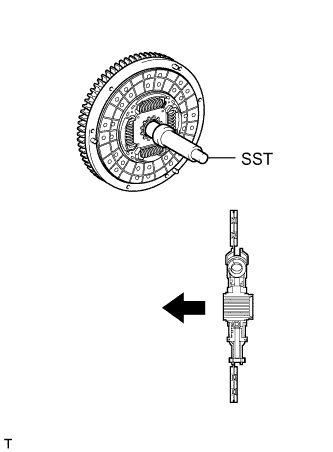
Insert SST into the clutch disc. Then insert SST (together with the clutch disc) into the flywheel to install the clutch disc.
- SST
- 09301-00110
Text in Illustration 
Flywheel Side Note
Be sure to install the clutch disc so that it is facing in the correct direction.
-
-
INSTALL CLUTCH COVER ASSEMBLY (for Manual Transmission)
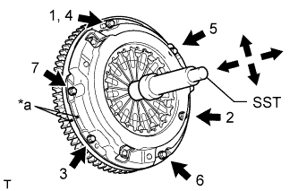
Text in Illustration *a Matchmark
-
Align the matchmarks on the clutch cover and flywheel.
-
Tighten the 6 bolts uniformly in the order shown in the illustration, starting with the bolt located near the knock pin on the top.
- SST
- 09301-00110
- Torque:
- 19 N*m { 194 kgf*cm, 14 ft.*lbf }
Tech Tips
Move SST up and down, and right and left lightly after checking that the clutch disc assembly is in the center, and then tighten the bolts.
-
-
INSPECT AND ADJUST CLUTCH COVER ASSEMBLY (for Manual Transmission)
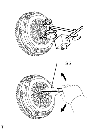
-
Using a dial indicator with a roller instrument, measure the diaphragm spring tip alignment.
- SST
- 09333-00013
Maximum non-alignment 0.5 mm (0.0196 in.)
-
If the alignment is more than the maximum, use SST to adjust the diaphragm spring tip alignment.
-
-
INSTALL DRIVE PLATE AND RING GEAR SUB-ASSEMBLY (for Automatic Transmission)
-
Using SST, hold the crankshaft.
- SST
- 09213-54015 ( 91651-60855 )
- 09330-00021
-
Text in Illustration *1 Front Drive Plate Spacer *2 Drive Plate and Ring Gear *3 Rear Drive Plate Spacer Transmission Side Install the front spacer, drive plate and rear spacer to the crankshaft.
Tech Tips
-
The front drive plate spacer is reversible.
-
As the rear drive plate spacer and drive plate and ring gear are not reversible, be sure to install it so that it is facing in the direction shown in the illustration.
-
-
Clean the bolts and bolt holes.
-
Apply adhesive to 2 or 3 threads at the end of each of the 10 bolts.
Adhesive Toyota Genuine Adhesive 1324, Three Bond 1324 or equivalent -
Install and uniformly tighten the 10 bolts in several steps in the sequence shown in the illustration.
- Torque:
- 74 N*m { 755 kgf*cm, 55 ft.*lbf }
Note
Do not start the engine for at least an hour after installing the drive plate.
-
-
INSTALL REAR NO. 1 ENGINE MOUNTING INSULATOR
Tech Tips
Perform this procedure only when replacement of the engine mounting insulator is necessary.
-
for Automatic Transmission:
-
Install the engine mounting insulator to the transmission with the 4 bolts.
- Torque:
- 65 N*m { 663 kgf*cm, 48 ft.*lbf }
-
Install the rear engine mounting heat insulator to the engine mounting insulator.
- Torque:
- 12 N*m { 122 kgf*cm, 9 ft.*lbf }
-
Install the frame crossmember to the rear engine mounting insulator with the 4 bolts.
- Torque:
- 30 N*m { 306 kgf*cm, 22 ft.*lbf }
-
-
for Manual Transmission:
-
Install the engine mounting insulator to the transmission with the 4 bolts.
- Torque:
- 65 N*m { 663 kgf*cm, 48 ft.*lbf }
-
Install the rear engine mounting heat insulator to the engine mounting insulator.
- Torque:
- 12 N*m { 122 kgf*cm, 9 ft.*lbf }
-
Install the frame crossmember to the rear engine mounting insulator with the 4 bolts.
- Torque:
- 30 N*m { 306 kgf*cm, 22 ft.*lbf }
-
-
-
INSTALL MANUAL TRANSMISSION ASSEMBLY (for Manual Transmission)
-
Install the manual transmission assembly Click here.
-
-
INSTALL AUTOMATIC TRANSMISSION ASSEMBLY (for Automatic Transmission)
-
Install the automatic transmission assembly Click here.
-
-
INSTALL STARTER ASSEMBLY
-
for 1.4 kW Type:
Install the starter assembly Click here.
-
for 2.0 kW Type:
Install the starter assembly Click here.
-
-
INSTALL DRIVE PLATE AND TORQUE CONVERTER CLUTCH SETTING BOLT (for Automatic Transmission)
-
Turn the crankshaft to gain access to the installation locations of the 6 torque converter clutch setting bolts and install each bolt while holding the crankshaft pulley bolt with a wrench.
- Torque:
- 48 N*m { 489 kgf*cm, 35 ft.*lbf }
Note
Install the black bolt first, and then the 5 silver bolts.
-
Install the flywheel housing dust seal.
-
-
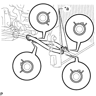
INSTALL FRONT PROPELLER SHAFT ASSEMBLY
-
Align the matchmarks on the yoke and differential flange.
-
Install the propeller shaft assembly with the 4 washers, 4 bolts and 4 nuts.
- Torque:
- 88 N*m { 899 kgf*cm, 65 ft.*lbf }
-
Align the matchmarks on the yoke and transfer flange.
-
Install the propeller shaft assembly with the 4 washers and 4 nuts.
- Torque:
- 88 N*m { 899 kgf*cm, 65 ft.*lbf }
-
-
INSTALL PROPELLER SHAFT ASSEMBLY
-
Align the matchmarks on the propeller shaft flange and differential flange.
-
Install the propeller shaft assembly with the 4 washer, 4 bolts and 4 nuts.
- Torque:
- 88 N*m { 899 kgf*cm, 65 ft.*lbf }
-
Align the matchmarks on the propeller shaft flange and transfer flange.
-
Install the propeller shaft assembly with the 4 washers and 4 nuts.
- Torque:
- 88 N*m { 899 kgf*cm, 65 ft.*lbf }
-
-
INSTALL FRONT EXHAUST PIPE ASSEMBLY
-
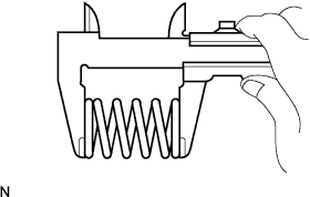
Using a vernier caliper, measure the free length of the compression spring.
Minimum free length 43 mm (1.69 in.) If the length is less than the minimum, replace the compression spring.
-
Install the front exhaust pipe to the pipe support.
-
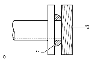
Text in Illustration *1 Gasket *2 Wooden Block Using a plastic-faced hammer and wooden block, tap in a new gasket until its surface is flush with the exhaust manifold.
Note
-
Be sure to install the gasket so that it faces the correct direction.
-
Do not reuse the gasket.
-
Do not damage the gasket.
-
When connecting the exhaust pipe, do not push in the gasket with the exhaust pipe.
-
-
Connect the front exhaust pipe to the exhaust manifold with the 2 compression springs and 2 bolts. Alternately tighten the bolts in several passes.
- Torque:
- 43 N*m { 438 kgf*cm, 32 ft.*lbf }
-
-
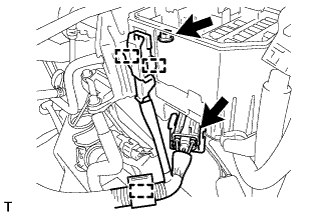
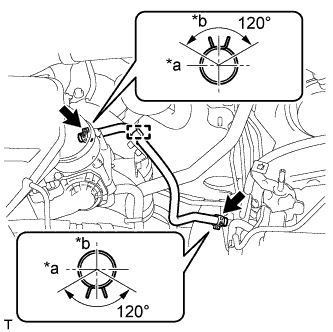
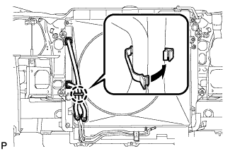
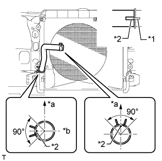
CONNECT ENGINE WIRE
-
Install the bracket to the engine mounting insulator LH with the bolt.
- Torque:
- 13 N*m { 131 kgf*cm, 9 ft.*lbf }
-
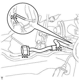
Attach the 3 clamps and connect the engine wire to the vehicle RH side.
-
Connect the ECM connector.
-
Attach the grommet to the wire harness support.
Text in Illustration *1 Grommet *2 Wire Harness Support -
Pass the wire harness into the vehicle and install the wire harness support.
-
Attach the clamp.
-
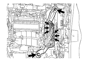
Connect the 9 connectors and attach the clamp.
-
Install the glove compartment door Click here.
-
-
Connect the connector and attach the clamp.
-
Connect the wire harness, attach the 2 clamps and install the nut.
- Torque:
- 11 N*m { 112 kgf*cm, 8 ft.*lbf }
-
Text in Illustration *a 45° or less Install the ground wire and engine wire with the 2 clamps and bolt.
- Torque:
- 22 N*m { 219 kgf*cm, 16 ft.*lbf }
-
-
INSTALL FRONT NO. 1 FENDER APRON TO FRAME SEAL LH
-
Install the front fender apron to frame seal with the 5 clips.
-
-
INSTALL FRONT NO. 1 FENDER APRON TO FRAME SEAL RH
-
Install the front No. 1 fender apron to frame seal with the 5 clips.
-
-
CONNECT COOLER COMPRESSOR ASSEMBLY
-
Temporarily install the cooler compressor with the 4 bolts.
-
Tighten the bolts in the order shown in the illustration to connect the cooler compressor.
- Torque:
- 25 N*m { 250 kgf*cm, 18 ft.*lbf }
-
Connect the connector.
-
Install the suction hose with the bolt.
- Torque:
- 7.8 N*m { 80 kgf*cm, 69 in.*lbf }
-
-
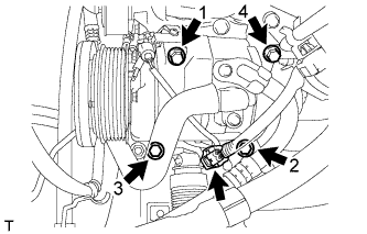
CONNECT VANE PUMP ASSEMBLY
-
Connect the vane pump with the 2 bolts.
- Torque:
- 21 N*m { 214 kgf*cm, 15 ft.*lbf }
-
Connect the 2 connectors.
-
Install the pressure feed tube with the bolt.
- Torque:
- 28 N*m { 285 kgf*cm, 21 ft.*lbf }
-
-
CONNECT HEATER HOSE
-
Using needle-nose pliers, grip the claws of the clamp and slide the 2 clamps to connect the heater hoses.
-
-
CONNECT UNION TO CHECK VALVE HOSE
-
Using needle-nose pliers, grip the claws of the clamp and slide the clamp to connect the check valve hose.
-
-
CONNECT PURGE LINE HOSE
-
Connect the purge line hose to the vacuum switching valve.
-
-
INSTALL NO. 2 FUEL HOSE
-
Text in Illustration *a Front *b Top Using needle-nose pliers, grip the claws of the clamp and slide the 2 clamps to connect the fuel hose.
Tech Tips
The direction of each hose clamp is indicated in the illustration.
-
Connect the fuel hose to the clamp.
-
-
INSTALL FUEL HOSE
-
Install the fuel hose Click here.
-
Connect the hose to the 2 clamps.
-
-
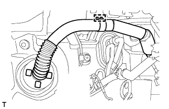
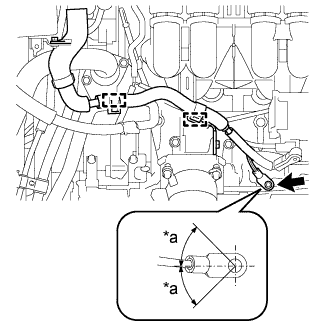
CONNECT NO. 1 OIL COOLER INLET HOSE AND NO. 1 OIL COOLER OUTLET HOSE (for Automatic Transmission)
Text in Illustration *a Pink Paint Mark
-
Connect the No. 1 oil cooler inlet hose and No. 1 oil cooler outlet hose to the oil cooler inlet tube and No. 1 oil cooler outlet tube.
-
Connect the 2 hoses to the No. 2 oil cooler tube to install them.
Note
-
When connecting the hoses to the tube, support the tube by hand and be careful to prevent the tube from being deformed.
-
Make sure the paint marks and pinching portion of each clip are facing the directions shown in the illustration.
-
-
-
INSTALL FAN SHROUD
-
Install the fan pulley to the water pump.
-
Place the shroud together with the coupling fan between the radiator and engine.
Note
Be careful not to damage the radiator core.
-
Temporarily install the fluid coupling fan to the water pump with the 4 nuts. Tighten the nuts as much as possible by hand.
-
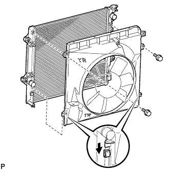
Attach the claws of the shroud to the radiator as shown in the illustration.
-
Install the shroud with the 2 bolts.
- Torque:
- 5.0 N*m { 51 kgf*cm, 44 in.*lbf }
-
Install the fan and generator V-belt Click here.
-
Tighten the 4 nuts of the fluid coupling fan.
- Torque:
- 25 N*m { 255 kgf*cm, 18 ft.*lbf }
-
Attach the claw to close the flexible hose clamp as shown in the illustration.
-
-
INSTALL NO. 2 RADIATOR HOSE
-
Text in Illustration *1 Protrusion *2 Paint Mark *a Top *b RH Side Install the No. 2 radiator hose so that its paint mark aligns with the radiator and water inlet protrusion as shown in the illustration.
Tech Tips
The direction of each hose clamp is indicated in the illustration.
-
-
INSTALL NO. 1 RADIATOR HOSE
-
Text in Illustration *1 Protrusion *2 Paint Mark *a Top *b LH Side Install the No. 1 radiator hose so that its paint marks align with the radiator and cylinder head protrusions as shown in the illustration.
Tech Tips
The direction of each hose clamp is indicated in the illustration.
-
-
INSTALL RADIATOR RESERVOIR
-
Install the radiator reservoir with the 3 bolts.
- Torque:
- 5.0 N*m { 51 kgf*cm, 44 in.*lbf }
-
Connect the reservoir hose to the radiator.
-
-
INSTALL NO. 1 AIR INJECTION SYSTEM HOSE
-
Using needle-nose pliers, grip the claws of the clamp and slide the 2 clamps to install the air injection system hose.
-
Install a new hose clamp.
-
-
INSTALL INTAKE AIR CONNECTOR
-
Install the intake air connector with the 3 bolts.
- Torque:
- 8.0 N*m { 82 kgf*cm, 71 in.*lbf }
-
Tighten the hose clamp.
- Torque:
- 5.0 N*m { 51 kgf*cm, 44 in.*lbf }
-
Connect the vacuum hose.
-
Attach the wire harness clamp.
-
Connect the No. 2 ventilation hose.
-
w/ Manifold absolute pressure sensor:
-
Connect the vacuum hose.
-
Attach the 2 clamps.
-
Connect the air pressure sensor connector.
-
-
-
INSTALL AIR CLEANER CASE
-
Install the air cleaner case with the 3 bolts.
- Torque:
- 12 N*m { 122 kgf*cm, 9 ft.*lbf }
-
Install the air cleaner filter element.
-
-
INSTALL AIR CLEANER CAP SUB-ASSEMBLY
-
Text in Illustration *1 Matchmark *a Upper Side *b Front Install the air cleaner hose, align its matchmark with the matchmark of the air cleaner cap as shown in the illustration.
-
Tighten the hose clamp.
- Torque:
- 5.0 N*m { 51 kgf*cm, 44 in.*lbf }
-
Attach the 4 clamps.
-
Install the ground wire and clamp with the bolt.
- Torque:
- 8.5 N*m { 87 kgf*cm, 75 in.*lbf }
-
Connect the mass air flow meter connector and attach the 3 clamps.
-
-
INSTALL COWL TOP VENTILATOR LOUVER SUB-ASSEMBLY
-
Install the cowl top ventilator louver Click here.
-
-
INSTALL HOOD SUB-ASSEMBLY
-
Install the hood with the 8 bolts.
- Torque:
- for bolt A
- 13 N*m { 133 kgf*cm, 10 ft.*lbf }
- for bolt B
- 18 N*m { 184 kgf*cm, 13 ft.*lbf }
Text in Illustration 
Bolt A 
Bolt B -
Connect the washer nozzle hose.
-
-
ADJUST HOOD SUB-ASSEMBLY
-
Adjust the hood position.
-
Loosen the 4 hinge bolts on the hood.
-
Move the hood and adjust the clearance between the hood and front fender.
-
Tighten the 4 hinge bolts on the hood.
- Torque:
- 13 N*m { 133 kgf*cm, 10 ft.*lbf }
-
-
Adjust the height of the front end of the hood using the cushion rubbers.
-
Adjust the 2 cushion rubbers so that the heights of the hood and fender are aligned.
Tech Tips
Raise or lower the front end of the hood by turning the 2 cushion rubbers.
-
-
Adjust the hood lock.
-
Loosen the 3 bolts.
-
Adjust the hood lock and tighten the 3 bolts.
- Torque:
- 7.5 N*m { 76 kgf*cm, 66 in.*lbf }
-
Check that the striker can smoothly engage with the hood lock.
-
-
-
CONNECT CABLE TO NEGATIVE BATTERY TERMINAL
Note
When disconnecting the cable, some systems need to be initialized after the cable is reconnected Click here.
-
ADD AUTOMATIC TRANSMISSION FLUID (for Automatic Transmission)
Fluid type Toyota Genuine ATF WS -
ADD ENGINE OIL
-
Clean and install the oil drain plug and a new gasket.
- Torque:
- 38 N*m { 382 kgf*cm, 28 ft.*lbf }
-
Add fresh engine oil.
Standard Oil Grade Oil Grade Oil Viscosity (SAE) API grade SL "energy-conserving", SM "energy-conserving", SN "resource-conserving" or ILSAC multigrade engine oil
-
0W-20
-
5W-20
-
5W-30
-
10W-30
API grade SL, SM or SN multigrade engine oil
-
15W-40
-
20W-50
Standard Capacity Item Specified Condition Drain and refill without oil filter change 5.0 liters (5.3 US qts, 4.4 Imp. qts) Drain and refill with oil filter change 5.7 liters (6.0 US qts, 5.0 Imp. qts) Dry fill 6.1 liters (6.4 US qts, 5.4 Imp. qts) -
-
Install the oil filler cap.
-
-
ADD ENGINE COOLANT
-
Tighten the cylinder block drain cock plug.
- Torque:
- 13 N*m { 130 kgf*cm, 9 ft.*lbf }
-
Tighten the radiator drain cock plug by hand.
-
Disconnect the 2 vinyl hoses.
-
Add engine coolant.
Standard Capacity Item Specified Condition for Automatic Transmission w/o Rear Heater 8.1 liters (8.6 US qts, 7.1 Imp. qts) w/ Rear Heater 9.9 liters (10.5 US qts, 8.7 Imp. qts) for Manual Transmission w/o Rear Heater 8.3 liters (8.8 US qts, 7.3 Imp. qts) w/ Rear Heater 10.1 liters (10.7 US qts, 8.9 Imp. qts) Note
Do not substitute plain water for engine coolant.
Tech Tips
-
TOYOTA vehicles are filled with TOYOTA SLLC at the factory. In order to avoid damage to the engine cooling system and other technical problems, only use TOYOTA SLLC or similar high quality ethylene glycol based non-silicate, non-amine, non-nitrite, non-borate coolant with long-life hybrid organic acid technology (coolant with long-life hybrid organic acid technology consists of a combination of low phosphates and organic acids).
-
Press the No. 1 and No. 2 radiator hoses several times by hand, and then check the coolant level. If the coolant level is low, add coolant.
-
-
Slowly pour coolant into the radiator reservoir until it reaches the F line.
-
Install the reservoir cap.
-
Install the radiator cap.*1
-
Start the engine and stop it immediately.*2
-
Allow approximately 10 seconds to pass. Then remove the radiator cap and check the coolant level. If the coolant level has decreased, add coolant.*3
-
Repeat steps *1, *2 and *3 until the coolant level does not decrease.
Tech Tips
Be sure to perform this step while the engine is cold, as air in the No. 1 radiator hose will flow into the radiator if the engine is warmed up and the thermostat opens.
-
Install the radiator cap.*4
-
Set the air conditioning as follows.*5
Item Condition Fan speed Any setting except off Temperature Toward WARM Air conditioning switch Off -
Start the engine, warm it up until the thermostat opens, and then continue to run the engine for several minutes to circulate the coolant.*6
CAUTION:
-
Wear protective gloves. Hot areas on the parts may injure your hands.
-
Be careful of the fan.
-
Be careful as the engine, radiator and radiator hoses are hot and can cause burns.
Note
-
Immediately after starting the engine, if the radiator reservoir does not have any coolant, perform the following: 1) stop the engine, 2) wait until the coolant has cooled down, and 3) add coolant until the coolant is filled to the F line.
-
Do not start the engine when there is no coolant in the radiator reservoir.
-
Pay attention to the needle of the engine coolant temperature receiver gauge. Make sure that the needle does not show an abnormally high temperature.
-
If there is not enough coolant, the engine may burn out or overheat.
Tech Tips
-
Press the No. 1 and No. 2 radiator hoses several times by hand to bleed air while warming up the engine.
-
The thermostat opening timing can be confirmed by pressing the No. 2 radiator hose by hand and checking when the engine coolant starts to flow inside the hose.
-
-
Stop the engine, wait until the engine coolant cools down to ambient temperature. Then remove the radiator cap and check the coolant level.*7
CAUTION:
Do not remove the radiator cap while the engine and radiator are still hot. Pressurized, hot engine coolant and steam may be released and cause serious burns.
-
If the coolant level has decreased, add coolant and warm up the engine until the thermostat opens.*8
-
If the coolant level has not decreased, check that the coolant level in the radiator reservoir is at the F line.
If the coolant level is below the F line, repeat steps *4 through *8.
If the coolant level is above the F line, drain coolant until the coolant level reaches the F line.
-
-
INSPECT SHIFT LEVER POSITION
-
When moving the shift lever from P to R with the ignition switch to ON and the brake pedal depressed, make sure that it moves smoothly and correctly into position.
-
Check that the shift lever does not stop when moving the shift lever from R to P, and check that the shift lever does not stick when moving the shift lever from D to L.
-
Start the engine and make sure that the vehicle moves forward after moving the shift lever from N to D and moves in reverse after moving the shift lever to R.
If the operation cannot be performed as specified, inspect the park/neutral position switch assembly and check the transmission floor shift assembly installation condition.
If the indicator and shift lever position do not match, carry out the following adjustment procedures.
-
-
INSPECT FOR OIL LEAK
-
Start the engine. Make sure that there are no oil leaks from the areas that were worked on.
-
-
INSPECT ENGINE OIL LEVEL
-
Warm up the engine, stop the engine and wait 5 minutes.
-
Check that the oil level is between the dipstick low level mark and full level mark.
If the level is low, check for leakage and add oil up to the full level mark.
Note
Do not fill engine oil above the full level mark.
-
-
INSPECT FOR COOLANT LEAK
CAUTION:
To avoid being burned, do not remove the radiator reservoir cap while the engine and radiator are still hot. Thermal expansion may cause hot engine coolant and steam to blow out from the radiator.
-
Fill the radiator with coolant and attach a radiator cap tester.
-
Warm up the engine.
-
Using the radiator cap tester, increase the pressure inside the radiator to 123 kPa (1.3 kgf/cm2, 18 psi), and then check that the pressure does not drop.
If the pressure drops, check the hose, radiator and water pump for leakage. If no external leakage is found, check the heater core, cylinder block and cylinder head.
-
-
INSPECT FOR FUEL LEAK
-
Make sure that there are no fuel leaks after performing maintenance on the fuel system.
-
Connect the intelligent tester to the DLC3.
-
Turn the ignition switch to ON and turn the intelligent tester on.
Note
Do not start the engine.
-
Enter the following menus: Powertrain / Engine and ECT / Active Test / Control the Fuel Pump / Speed.
-
Check that there are no leaks from the fuel system.
If there are fuel leaks, repair or replace parts as necessary.
-
Turn the ignition switch off.
-
Disconnect the intelligent tester from the DLC3.
-
-
-
INSPECT FOR EXHAUST GAS LEAK
If gas is leaking, tighten the areas necessary to stop the leak. Replace damaged parts as necessary.
-
INSPECT IGNITION TIMING
-
Warm up and stop the engine.
-
When using an intelligent tester:
-
Connect the intelligent tester to the DLC3.
-
Start the engine and idle it.
-
Turn the intelligent tester on.
-
Enter the following menus: Powertrain / Engine and ECT / Data List / IGN Advance.
Standard ignition timing 5 to 15° BTDC @ idle Tech Tips
Refer to the intelligent tester operator's manual for further details.
Note
-
When checking the ignition timing, the transaxle should be in neutral or park.
-
Switch off all the accessories and the A/C before connecting the intelligent tester.
-
-
Check that the ignition timing advances immediately when the engine speed is increased.
-
Enter the following menus: Powertrain / Engine and ECT / Active Test / Connect the TC and TE1.
-
Monitor IGN Advance.
-
Perform the Active Test.
Standard ignition timing 3 to 7° BTDC @ idle Tech Tips
Refer to the intelligent tester operator's manual for further details.
Note
When checking the ignition timing, the transmission should be in neutral or park.
-
-
When not using the intelligent tester:
-
Loosen the hose clamp from the throttle body side.
-
Remove the 3 bolts and disconnect the intake air connector.
Tech Tips
Move the intake air connector so that the tester probe of a timing light can be connected to the wire of the ignition coil for the No. 1 cylinder.
-
Connect the tester probe of a timing light to the wire of the ignition coil connector for the No. 1 cylinder.
Note
Use a timing light that detects primary signals.
-
Connect the intake air connector.
Tech Tips
Return the parts to their original positions so that the engine can be started.
-
Start the engine and idle it.
-
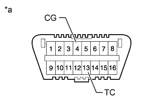
Text in Illustration *a Front view of DLC3 Using SST, connect terminals 13 (TC) and 4 (CG) of the DLC3.
- SST
- 09843-18040
Note
-
Confirm the terminal numbers before connecting them. Connecting the wrong terminals can damage the engine.
-
When checking the ignition timing, the shift lever should be in neutral or P.
-
Using the timing light, check the ignition timing.
Standard ignition timing 3 to 7° BTDC @ idle Note
-
Turn all the electrical systems and the A/C off.
-
When checking the ignition timing, the shift lever should be in neutral or P.
-
-
Remove SST from the DLC3.
-
Check the ignition timing.
Standard ignition timing 5 to 15° BTDC @ idle -
Check that the ignition timing advances immediately when the engine speed is increased.
-
Turn the ignition switch off.
-
Disconnect the timing light from the engine.
-
Connect the intake air connector with the 3 bolts.
- Torque:
- 8.0 N*m { 82 kgf*cm, 71 in.*lbf }
-
Tighten the hose clamp.
- Torque:
- 5.0 N*m { 51 kgf*cm, 44 in.*lbf }
-
-
-
INSPECT ENGINE IDLE SPEED
-
Warm up and stop the engine.
-
When using the intelligent tester:
-
Connect the intelligent tester to the DLC3.
-
Start the engine and idle it.
-
Turn the intelligent tester on.
-
Enter the following menus: Powertrain / Engine and ECT / Data List / Engine Speed.
Standard idle speed 600 to 700 rpm Tech Tips
Refer to the intelligent tester operator's manual for further details.
Note
-
Turn all the electrical systems and the A/C off.
-
When checking the idling speed, the shift lever should be in neutral or P.
-
-
Turn the ignition switch off.
-
Disconnect the intelligent tester from the DLC3.
-
-
Text in Illustration *a Front view of DLC3 When not using the intelligent tester:
-
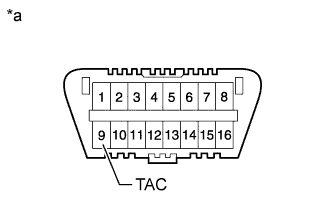
Using SST, connect a tachometer probe to terminal 9 (TAC) of the DLC3.
- SST
- 09843-18040
Note
-
Confirm the terminal numbers before connecting them. Connecting the wrong terminals can damage the engine.
-
Turn all the electrical systems and the A/C off.
-
When checking the idling speed, the shift lever should be in neutral or P.
-
Check the idle speed.
Standard idle speed 600 to 700 rpm -
Disconnect the tachometer probe from the DLC3.
-
-
If the engine speed is not as specified, update the idle speed control (ISC) learned value using either procedure 1 or procedure 2 below, and then check the engine speed again.
-
Procedure 1:
After completely warming up the engine, drive the vehicle at 30 km/h (19 mph) for 30 seconds or more and idle the engine for 30 seconds or more. Repeat this pattern 5 times or more.
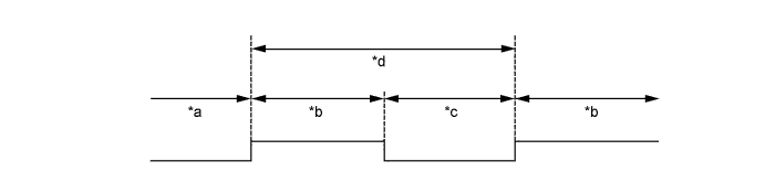
Text in Illustration *a Engine completely warmed up *b Vehicle being driven at 30 km/h (19 mph) *c Idling *d 1 time -
Procedure 2:
After completely warming up the engine, stop the engine and then idle it. Repeat this pattern 5 times or more.

Text in Illustration *a Engine completely warmed up *b Engine stopped *c Engine started *d Idling *e 1 time - - Tech Tips
-
Be sure to idle the engine for 150 seconds or more for each time the pattern is repeated.
-
If the engine speed is not as specified after performing the procedure above, inspect the idle speed control system as it is malfunctioning.
-
-
-
-
INSPECT CO/HC
-
Start the engine.
-
Run the engine at 2500 rpm for approximately 180 seconds.
-
Insert a CO/HC meter testing probe at least 40 cm (1.31 ft.) into the tailpipe while idling the engine.
-
Check the CO/HC concentration during idling and when the engine is running at 2500 rpm.
Tech Tips
When doing the 2 mode (with the engine idling/ running at 2500 rpm) test, the measuring procedures are determined by applicable local regulations.
If the CO/HC concentration does not comply with regulations, troubleshoot in the order given below.
-
Check the air fuel ratio sensor Click here and heated oxygen sensor Click here.
-
Refer to the table below for possible causes, and then inspect the applicable parts and repair them if necessary.
CO HC Problems Possible Causes Normal High Rough idling
-
Faulty ignition:
-
Incorrect timing
-
Plugs are contaminated or shorted, or gaps are incorrect
-
Incorrect valve clearance
-
Leakage from intake or exhaust valves
-
Leakage from cylinders
Low High Rough idling
(Fluctuating HC reading)
-
Vacuum leaks:
-
PCV hoses
-
Intake manifold
-
Throttle body
-
Brake booster line
-
Lean mixture causing misfire
High High Rough idling
(Black smoke from exhaust)
-
Restricted air cleaner filter element
-
Plugged PCV valve
-
Faulty SFI system:
-
Faulty pressure regulator
-
Faulty engine coolant temperature sensor
-
Faulty mass air flow meter
-
Faulty ECM
-
Faulty injectors
-
Faulty throttle body
-
-
-
-
INSTALL UPPER RADIATOR SUPPORT SEAL
-
Install the upper radiator support seal with the 13 clips.
-
-
INSTALL REAR ENGINE UNDER COVER ASSEMBLY
-
Install the rear engine under cover with the 4 bolts.
- Torque:
- 29 N*m { 296 kgf*cm, 21 ft.*lbf }
-
-
INSTALL TRANSMISSION UNDER COVER
-
Install the transmission under cover with the 2 bolts.
- Torque:
- 29 N*m { 296 kgf*cm, 21 ft.*lbf }
-
-
INSTALL NO. 1 ENGINE UNDER COVER SUB-ASSEMBLY
-
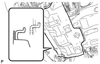
Hook the engine under cover to the vehicle body as shown in the illustration.
-
Install the 4 bolts.
- Torque:
- 29 N*m { 296 kgf*cm, 21 ft.*lbf }
-
-
INSTALL FRONT BUMPER COVER LOWER
-
Install the front bumper cover lower with the 5 bolts and clip.
- Torque:
- 8.0 N*m { 82 kgf*cm, 71 in.*lbf }
-
-
INSPECT ENGINE COOLANT LEVEL
-
The engine coolant should be between the LOW and FULL lines when the engine is cold.
If the engine coolant is below the LOW line, check for leakage and add TOYOTA Super Long Life Coolant (SLLC) or similar high quality ethylene glycol based non-silicate, non-amine, non-nitrite, non-borate coolant with long-life hybrid organic acid technology to the FULL line.
-