ENGINE UNIT REMOVAL

-
REMOVE IGNITION COIL ASSEMBLY
-
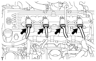
Disconnect the 4 ignition coil connectors.
-
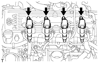
Remove the 4 bolts and 4 ignition coils.
-
-
REMOVE GENERATOR ASSEMBLY
-
for 80 A Type:
Remove the generator Click here.
-
for 100 A Type:
Remove the generator Click here.
-
-
REMOVE NO. 1 EXHAUST MANIFOLD HEAT INSULATOR
-
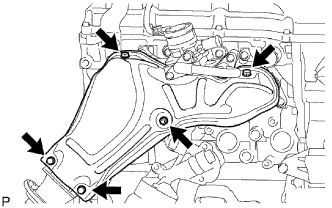
Remove the 5 bolts and No. 1 exhaust manifold heat insulator.
Tech Tips
-
It is only necessary to move the No. 1 exhaust manifold heat insulator so that the intake pipe can be removed in a later step.
-
It is not possible to fully remove the No. 1 exhaust manifold heat insulator in this step.
-
-
-
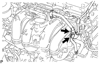
REMOVE NO. 4 INTAKE PIPE
-
Remove the 4 nuts, No. 4 intake pipe and 2 gaskets.
Note
Be careful not to damage the installation surface of the gaskets.
-
-
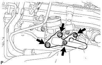
REMOVE AIR SWITCHING VALVE ASSEMBLY
-
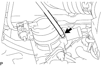
w/ Manifold Absolute Pressure Sensor:
Disconnect the vacuum hose.
-
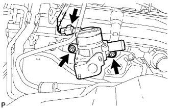
Disconnect the connector.
-
Remove the 2 nuts and air switching valve.
-
Remove the No. 1 exhaust manifold heat insulator.
-
-
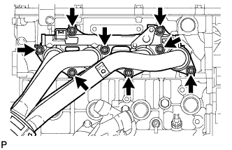
REMOVE EXHAUST MANIFOLD
-
Remove the 8 nuts and exhaust manifold.
-
Remove the gasket.
-
-
REMOVE THROTTLE WITH MOTOR BODY ASSEMBLY
-
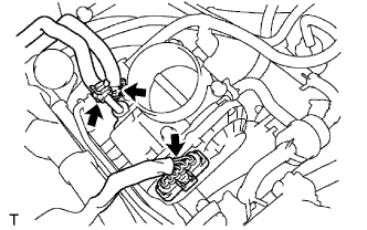
Disconnect the water by-pass hose.
-
Disconnect the No. 2 water by-pass hose.
-
Disconnect the throttle position sensor and throttle control motor connector.
-
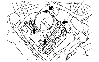
Remove the 2 bolts, 2 nuts and throttle body with motor.
-
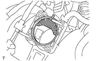
Remove the gasket from the intake manifold.
-
-
REMOVE FUEL DELIVERY PIPE WITH FUEL INJECTOR
-
Remove the fuel delivery pipe with fuel injector Click here.
-
-
REMOVE PURGE VSV
-
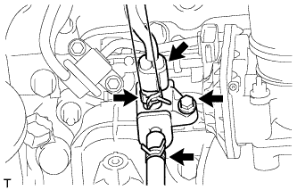
Disconnect the purge VSV connector.
-
Disconnect the 2 purge line hoses from the purge VSV.
-
Remove the bolt and purge VSV.
-
-
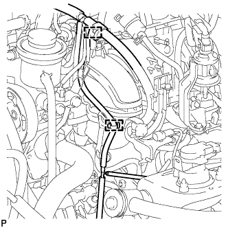
REMOVE INTAKE MANIFOLD
-
for Engine Front Side:
Detach the 2 wire harness clamps from the 2 wire harness clamp brackets.
-
for Engine Rear Side:
Detach the No. 2 water by-pass hose and disconnect the No. 3 ventilation hose from the intake manifold.
-
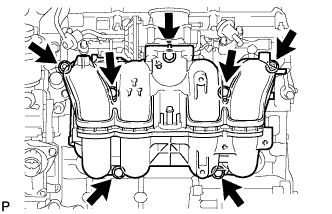
Remove the 5 bolts, 2 nuts and intake manifold.
-
Remove the gasket from the intake manifold.
-
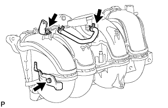
Remove the 2 bolts, 2 wire harness clamp brackets and No. 2 fuel vapor feed hose from the intake manifold.
-
-
REMOVE NO. 1 COMPRESSOR MOUNTING BRACKET
-
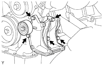
Remove the 5 bolts and compressor mounting bracket.
-
-
REMOVE NO. 1 IDLER PULLEY SUB-ASSEMBLY
-
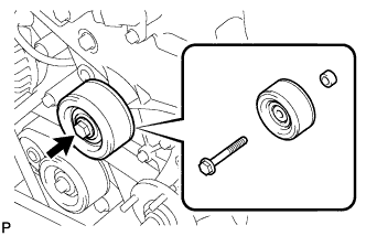
Remove the bolt, idler pulley and spacer.
-
-
REMOVE NO. 1 WATER BY-PASS PIPE
-
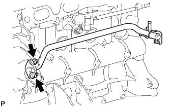
Remove the 2 nuts, water by-pass pipe and gasket.
-
-
REMOVE ENGINE OIL LEVEL DIPSTICK GUIDE
-
Remove the oil level dipstick.
-
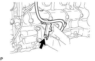
Remove the bolt and oil level dipstick guide.
-
-
REMOVE FRONT ENGINE MOUNTING INSULATOR
-
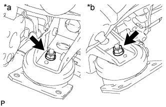
Text in Illustration *a LH Side *b RH Side Remove the 2 nuts and 2 engine mounting insulators.
-
-
REMOVE FRONT NO. 1 ENGINE MOUNTING BRACKET LH
-
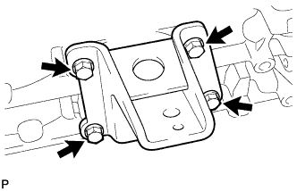
Remove the 4 bolts and engine mounting bracket.
-
-
REMOVE FRONT NO. 1 ENGINE MOUNTING BRACKET RH
-
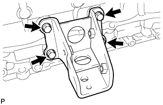
Remove the 4 bolts and engine mounting bracket.
-