CYLINDER BLOCK DISASSEMBLY

-
REMOVE CYLINDER BLOCK OIL ORIFICE
-
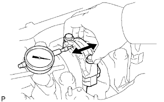
INSPECT CONNECTING ROD THRUST CLEARANCE
-
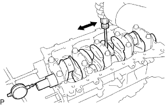
Using a dial indicator, measure the thrust clearance while moving the connecting rod back and forth.
Standard thrust clearance 0.1 to 0.3 mm (0.00394 to 0.0118 in.) Maximum thrust clearance 0.4 mm (0.0157 in.) If the thrust clearance is more than the maximum, replace the connecting rod assembly. If necessary, replace the crankshaft.
-
-
INSPECT CONNECTING ROD OIL CLEARANCE
-
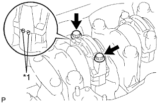
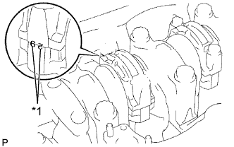
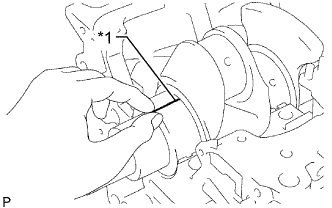
Text in Illustration *1 Matchmark Check the matchmarks on the connecting rod and cap to ensure correct reassembly.
-
Remove the 2 connecting rod cap bolts.
-
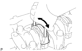
Using the 2 removed connecting rod bolts, move the connecting rod cap back and forth to remove the connecting rod cap.
-
Remove the lower bearing from the connecting rod cap.
Tech Tips
Keep the lower bearing and connecting rod cap together.
-
Clean the crank pin and bearings.
-
Check the crank pin and bearings for pitting and scratches.
If the crank pin or a bearing is damaged, replace the bearings. If necessary, grind or replace the crankshaft.
-
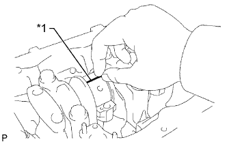
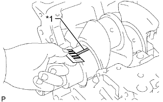
Text in Illustration *1 Plastigage Lay a strip of Plastigage across the crank pin.
-
Text in Illustration *1 Matchmark Install the connecting rod cap Click here.
Note
Do not turn the crankshaft.
-
Remove the 2 bolts, connecting rod cap and lower bearing.
-
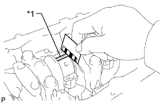
Text in Illustration *1 Plastigage 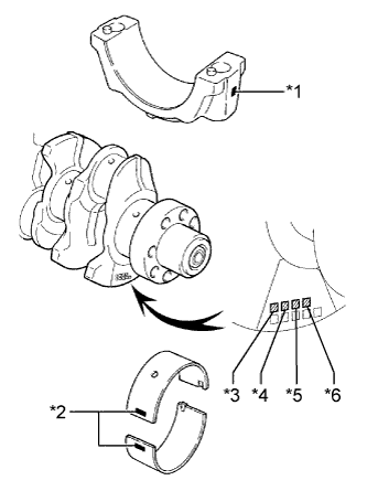
Text in Illustration *1 Mark 1, 2 or 3 *2 Mark 2, 3 or 4 *3 No. 1 *4 No. 2 *5 No. 3 *6 No. 4 Measure the Plastigage at its widest point.
Standard Oil Clearance Item Specified Condition STD 0.036 to 0.054 mm (0.00142 to 0.00212 in.) U/S 0.25, U/S 0.50 0.037 to 0.077 mm (0.00146 to 0.00303 in.) Maximum oil clearance 0.1 mm (0.00394 in.) If the oil clearance is more than the maximum, replace the bearings. If necessary, grind or replace the crankshaft.
Tech Tips
If using a standard bearing, replace it with one that has the same number. If the number of the bearing cannot be determined, select the correct bearing by adding together the numbers imprinted on the crankshaft and connecting rod cap, and then selecting the bearing with the same number as the total. There are 5 sizes of standard bearings, marked 2, 3, 4, 5 and 6.
Item Number Mark Connecting rod cap 1 2 3 Crankshaft 1 2 3 1 2 3 1 2 3 Use bearing 2 3 4 3 4 5 4 5 6 EXAMPLE:
Connecting rod cap 3 + Crankshaft 1 =
Total number 4 (Use bearing 4)
Reference Standard Connecting Rod Big End Inside Diameter Item Specified Condition Mark 1 62.014 to 62.020 mm (2.4415 to 2.4417 in.) Mark 2 62.020 to 62.026 mm (2.4417 to 2.4420 in.) Mark 3 62.026 to 62.032 mm (2.4420 to 2.4422 in.) Standard Crank Pin Diameter Item Specified Condition Mark 1 58.994 to 59.000 mm (2.3226 to 2.3228 in.) Mark 2 58.988 to 58.994 mm (2.3224 to 2.3226 in.) Mark 3 58.982 to 58.988 mm (2.3221 to 2.3224 in.) Standard Sized Connecting Rod Bearing Center Wall Thickness Item Specified Condition Mark 2 1.486 to 1.489 mm (0.0585 to 0.0586 in.) Mark 3 1.489 to 1.492 mm (0.0586 to 0.0587 in.) Mark 4 1.492 to 1.495 mm (0.0587 to 0.0589 in.) Mark 5 1.495 to 1.498 mm (0.0589 to 0.0590 in.) Mark 6 1.498 to 1.501 mm (0.0590 to 0.0591 in.) -
Completely remove the Plastigage.
-
-
REMOVE PISTON AND CONNECTING ROD
-
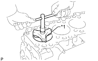
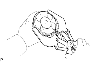
Text in Illustration *1 Ridge Reamer Using a ridge reamer, remove all the carbon from the top of the cylinder.
-
Push the piston, connecting rod assembly and upper bearing through the top of the cylinder block to remove them.
-
Remove the upper bearing from the connecting rod.
Tech Tips
-
Keep the bearings, connecting rod and cap together.
-
Be sure to organize the removed piston and connecting rod assemblies in such a way that they can be reinstalled exactly as before.
-
-
-
REMOVE CONNECTING ROD BEARING SET
-
Remove the connecting rod bearings from the connecting rods and connecting rod caps.
Tech Tips
Arrange the removed parts in the correct order.
-
-
REMOVE PISTON RING SET
-
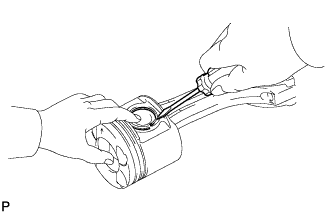
Using a piston ring expander, remove the 2 piston rings.
Tech Tips
Be sure to organize the removed piston rings in such a way that they can be reinstalled exactly as before.
-
Remove the coil and oil ring by hand.
-
-
REMOVE PISTON WITH PIN SUB-ASSEMBLY
-
Using a small screwdriver, pry out the 2 snap rings from the piston.
-
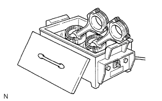
Gradually heat the piston to approximately 80°C (176°F).
-
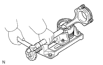
Using a plastic-faced hammer and brass bar, lightly tap out the piston pin. Then remove the connecting rod.
Tech Tips
-
The piston and pin are a matched set.
-
Be sure to organize the removed pistons, pins, rings, connecting rods and bearings in such a way that the parts can be reinstalled exactly as before.
-
-
-
INSPECT CRANKSHAFT THRUST CLEARANCE
-
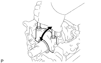
Using a dial indicator, measure the thrust clearance while prying the crankshaft back and forth with a screwdriver.
Standard thrust clearance 0.04 to 0.24 mm (0.00157 to 0.00945 in.) Maximum thrust clearance 0.3 mm (0.0118 in.) If the thrust clearance is more than the maximum, replace the thrust washers as a set.
Standard Thrust Washer Thickness Item Specified Condition STD 2.430 to 2.480 mm (0.0957 to 0.0976 in.) O/S 0.125 2.555 to 2.605 mm (0.1005 to 0.1025 in.) O/S 0.250 2.680 to 2.730 mm (0.1055 to 0.1074 in.)
-
-
INSPECT CRANKSHAFT OIL CLEARANCE
-
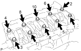
Uniformly loosen and remove the 10 crankshaft bearing cap bolts in several passes in the sequence shown in the illustration.
-
Using the removed crankshaft bearing cap bolts, pry the cap back and forth and remove the crankshaft bearing caps, lower crankshaft bearings and lower thrust washers (No. 5 crankshaft bearing cap only).
Tech Tips
-
Keep the lower bearing and crankshaft bearing cap together.
-
Be sure to organize the bearing caps and lower thrust washers (No. 5 crankshaft bearing only) in such a way that they can be reinstalled exactly as before.
-
-
Lift out the crankshaft.
-
Clean each main journal and bearing.
-
Check each crankshaft journal and bearing for pitting and scratches.
If the journal or a bearing is damaged, replace the bearings for that journal. If necessary, grind or replace the crankshaft.
-
Place the crankshaft on the cylinder block.
-
Text in Illustration *1 Plastigage Lay a strip of Plastigage across each journal.
-
Install the crankshaft bearing caps Click here.
Note
Do not turn the crankshaft.
-
Remove the crankshaft bearing caps.
-
Text in Illustration *1 Plastigage 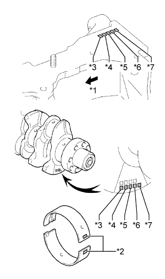
Text in Illustration *1 Front *2 Mark 2, 3, 4, 5 or 6 *3 No. 1 *4 No. 2 *5 No. 3 *6 No. 4 *7 No. 5 Measure the Plastigage at its widest point.
Standard Oil Clearance Item Specified Condition STD 0.030 to 0.048 mm (0.00118 to 0.00189 in.) O/S 0.25, O/S 0.50 0.037 to 0.077 mm (0.00146 to 0.00303 in.) Maximum oil clearance 0.1 mm (0.00394 in.) If the oil clearance is more than the maximum, replace the bearings. If necessary, grind or replace the crankshaft.
Tech Tips
If replacing the cylinder block sub-assembly, the bearing oil clearance will be within the standard range.
Standard oil clearance 0.030 to 0.048 mm (0.00118 to 0.00189 in.) Tech Tips
If using a standard bearing, replace it with one that has the same number. If the number of the bearing cannot be determined, select the correct bearing by adding together the numbers imprinted on the cylinder block and crankshaft, and then selecting the bearing with the same number as the total. There are 5 sizes of standard bearings, marked 2, 3, 4, 5 and 6.
Item Number Mark Cylinder block 1 2 3 Crankshaft 1 2 3 1 2 3 1 2 3 Use bearing 2 3 4 3 4 5 4 5 6 EXAMPLE:
Cylinder block 2 + crankshaft 1 =
Total number 3 (Use bearing 3)
Reference Standard Cylinder Block Main Journal Bore Diameter Item Specified Condition Mark 1 75.000 to 75.006 mm (2.9528 to 2.9530 in.) Mark 2 75.006 to 75.012 mm (2.9530 to 2.9532 in.) Mark 3 75.012 to 75. 018 mm (2.9532 to 2.9535 in.) Standard Crankshaft Journal Diameter Item Specified Condition Mark 1 69.994 to 70.000 mm (2.7557 to 2.7559 in.) Mark 2 69.988 to 69.994 mm (2.7554 to 2.7557 in.) Mark 3 69.982 to 69.988 mm (2.7552 to 2.7554 in.) Standard Sized Main Bearing Center Wall Thickness Item Specified Condition Mark 2 2.482 to 2.485 mm (0.0977 to 0.0978 in.) Mark 3 2.485 to 2.488 mm (0.0978 to 0.0980 in.) Mark 4 2.488 to 2.491 mm (0.0980 to 0.0981 in.) Mark 5 2.491 to 2.494 mm (0.0981 to 0.0982 in.) Mark 6 2.494 to 2.497 mm (0.0982 to 0.0983 in.) -
Completely remove the Plastigage.
-
-
REMOVE CRANKSHAFT
-
Lift out the crankshaft.
-
Remove the upper bearings and upper thrust washers (No. 5 crankshaft bearing only) from the cylinder block.
Tech Tips
Arrange the bearing caps, bearings and thrust washers (No. 5 crankshaft bearing only) in the correct order.
-
-
REMOVE NO. 1 OIL NOZZLE SUB-ASSEMBLY
-
Remove the 4 check valves and 4 oil nozzles.
-
-
REMOVE STUD BOLT
Tech Tips
If a stud bolt is deformed or the threads are damaged, replace it.
-
Remove the stud bolts.
-