ENGINE UNIT (w/o DPF) INSTALLATION

Note
-
When replacing the injectors (including shuffling the injectors between the cylinders), common rail or cylinder head, it is necessary to replace the injection pipes with new ones.
-
When replacing the fuel supply pump, common rail, cylinder block, cylinder head, cylinder head gasket or timing gear case, it is necessary to replace the fuel inlet pipe with a new one.
-
INSTALL FRONT NO. 1 ENGINE MOUNTING BRACKET RH
-
Install the 2 engine mounting brackets with the 8 bolts.
- Torque:
- 68 N*m { 694 kgf*cm, 50 ft.*lbf }
-
-
INSTALL NO. 2 CYLINDER BLOCK INSULATOR
-
Install the No. 2 cylinder block insulator.
-
-
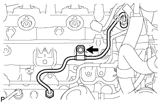
INSTALL NO. 1 VACUUM PIPE
-
Install the No. 1 vacuum pipe with the bolt.
- Torque:
- 8.0 N*m { 82 kgf*cm, 70 in.*lbf }
-
-
INSTALL NO. 1 OIL PAN COVER SUB-ASSEMBLY
-
Install the No. 1 oil pan cover with the 4 bolts.
- Torque:
- 9.0 N*m { 92 kgf*cm, 80 in.*lbf }
-
-
INSTALL NO. 1 VACUUM TRANSMITTING PIPE SUB-ASSEMBLY
-
Install the No. 1 vacuum transmitting pipe with the bolt and nut.
- Torque:
- for bolt
- 13 N*m { 133 kgf*cm, 10 ft.*lbf }
- for nut
- 8.0 N*m { 82 kgf*cm, 71 in.*lbf }
-
-
INSTALL OIL COOLER COVER SUB-ASSEMBLY
-
Install the oil cooler cover with the 13 bolts.
- Torque:
- 13 N*m { 133 kgf*cm, 10 ft.*lbf }
-
-
INSTALL NO. 2 VACUUM TRANSMITTING PIPE SUB-ASSEMBLY
-
Install the No. 2 vacuum transmitting pipe with the 2 nuts.
- Torque:
- 13 N*m { 133 kgf*cm, 10 ft.*lbf }
-
Connect the vacuum hose.
-
-
INSTALL NO. 3 VACUUM TRANSMITTING PIPE SUB-ASSEMBLY
-
Install the No. 3 vacuum transmitting pipe with the bolt.
- Torque:
- 18 N*m { 184 kgf*cm, 13 ft.*lbf }
-
Connect the vacuum hose.
-
-
INSTALL OIL FILTER SUB-ASSEMBLY
-
Check and clean the oil filter installation surface.
-
Apply clean engine oil to the gasket of a new oil filter.
-
Lightly screw the oil filter into place by hand. Tighten it until the gasket contacts the seat.
-
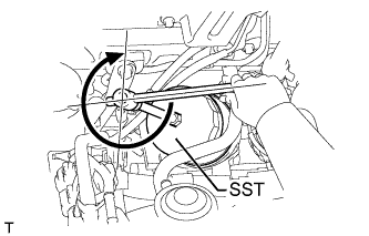
Using SST, tighten the oil filter. Depending on the space available, choose from the following.
- SST
- 09228-07501
-
If enough space is available, use a torque wrench to tighten the oil filter.
- Torque:
- 17 N*m { 173 kgf*cm, 13 ft.*lbf }
-
If enough space is not available to use a torque wrench, tighten the oil filter 3/4 of a turn by hand or with a common wrench.
-
-
INSTALL NO. 1 INJECTION PUMP PROTECTOR
-
Install the No. 1 injection pump protector with the 2 bolts.
- Torque:
- 29 N*m { 296 kgf*cm, 21 ft.*lbf }
-
-
INSTALL SUPPLY PUMP ASSEMBLY
-
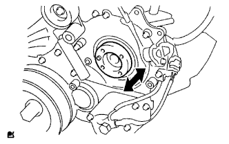
Check that the injection gear in the timing gear case moves back and forth smoothly.
-
Install the pump drive shaft pulley and No. 2 camshaft timing pulley flange with the 4 bolts.
- Torque:
- 31 N*m { 316 kgf*cm, 23 ft.*lbf }
-
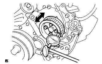
Move the pump drive shaft pulley back and forth to check the thrust clearance of the injection pump drive shaft.
Standard thrust clearance 0.15 to 0.55 mm (0.00590 to 0.0217 in.) If the clearance is not within the specified range, disassemble and reassemble the supply pump and pump drive shaft pulley. Then repeat the step above.
-
-
INSTALL COMMON RAIL ASSEMBLY
-
Install the common rail with the 2 bolts.
- Torque:
- 38 N*m { 387 kgf*cm, 28 ft.*lbf }
-
-
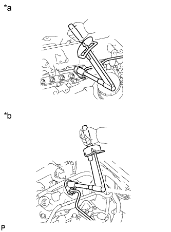
INSTALL FUEL INLET PIPE SUB-ASSEMBLY
-
Temporarily install the fuel inlet pipe with the union nuts.
Note
-
When replacing the fuel supply pump, it is necessary to replace the fuel inlet pipe with a new one.
-
Keep the fuel inlet pipe free of foreign matter.
-
-
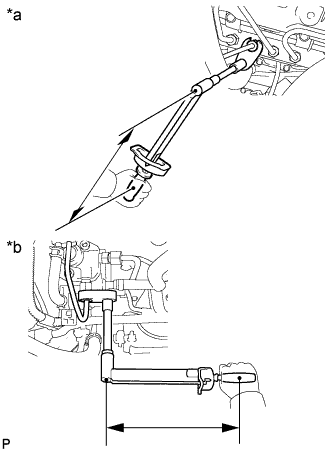
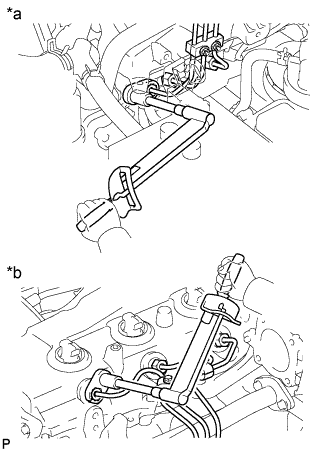
Text in Illustration *a for Common Rail Side *b for Fuel Supply Pump Side Using a 17 mm union nut wrench, tighten the fuel inlet pipe union nut on the common rail side.
- Torque:
- 35 N*m { 357 kgf*cm, 26 ft.*lbf }
Note
Use the formula to calculate special torque values for situations where a union nut wrench is combined with a torque wrench Click here.
-
Using a 17 mm union nut wrench, tighten the fuel inlet pipe union nut on the fuel supply pump side.
- Torque:
- 35 N*m { 357 kgf*cm, 26 ft.*lbf }
Note
Use the formula to calculate special torque values for situations where a union nut wrench is combined with a torque wrench Click here.
-
-
INSTALL NO. 2 INTAKE MANIFOLD INSULATOR
-
Install the No. 2 intake manifold insulator.
-
-
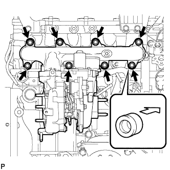
INSTALL INTAKE MANIFOLD
-
Temporarily install a new gasket and the intake manifold with the 2 nuts and 4 bolts.
-
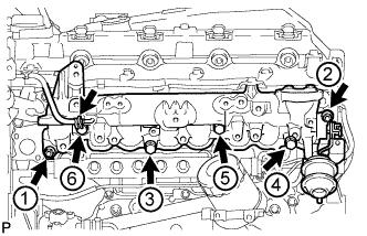
Tighten the 2 nuts and 4 bolts in the order shown in the illustration.
- Torque:
- 29 N*m { 296 kgf*cm, 21 ft.*lbf }
Note
-
When installing the intake manifold, make sure that the No. 1 intake manifold insulator is not pinched.
-
Make sure that the swirl control valve actuator is not damaged by the surrounding parts.
Text in Illustration *1 No. 1 Intake Manifold Insulator
-
Connect the vacuum hose to the intake manifold.
-
Attach the sensor wire connector clamp to the intake manifold.
-
-
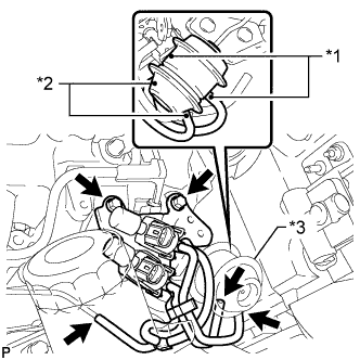
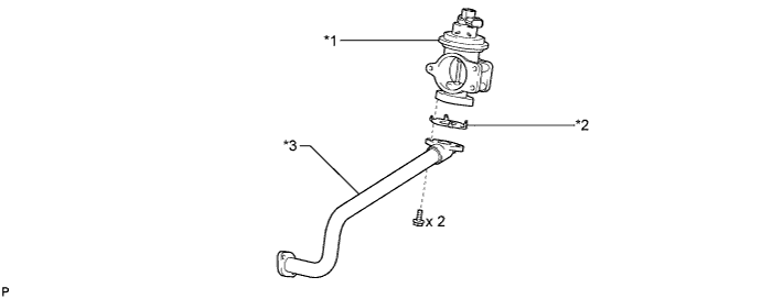
INSTALL INTAKE MANIFOLD INSULATOR
-
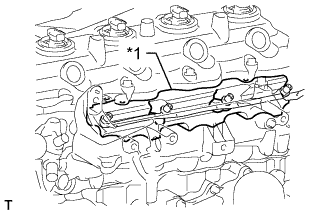
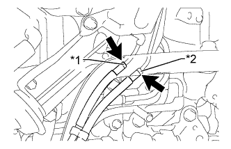
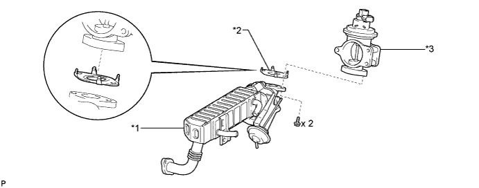
Text in Illustration *1 Intake Manifold *2 Intake Manifold Insulator *3 Common Rail Install the intake manifold insulator with the 2 bolts.
- Torque:
- 8.0 N*m { 82 kgf*cm, 71 in.*lbf }
-
-
INSTALL NO. 2 NOZZLE LEAKAGE PIPE ASSEMBLY
-
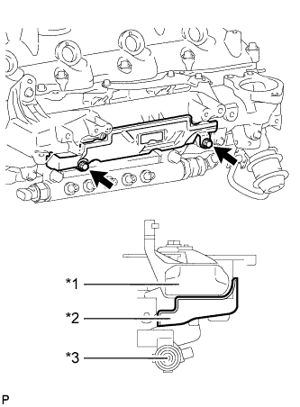
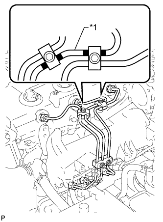
Text in Illustration *1 Union Bolt Temporarily install the No. 2 nozzle leakage pipe with the 4 bolts.
-
Temporarily install a new gasket and the union bolt.
-
Tighten the 4 bolts and union bolt.
- Torque:
- for bolt
- 13 N*m { 130 kgf*cm, 9 ft.*lbf }
- for union bolt
- 21 N*m { 214 kgf*cm, 15 ft.*lbf }
-
Connect the 3 fuel hoses.
-
-
INSTALL NO. 4 INJECTION PIPE SUB-ASSEMBLY
Note
-
When replacing an injector, it is necessary to replace the 4 injection pipes with new ones.
-
Keep the joints of the injection pipe clean.
-
Temporarily install the No. 4 injection pipe with the union nuts.
-
Install the bolt.
- Torque:
- 5.0 N*m { 51 kgf*cm, 44 in.*lbf }
Note
-
If an injection pipe clamp is removed from the No. 4 injection pipe, replace the injection clamp with a new one.
-
Make sure that the inner-rubbers of the injection pipe fit inside the clamps.
-
When installing the pipe, check that the inner-rubbers and the clamps are in their proper positions.
-
Text in Illustration *a Common Rail Side *b Injector Side Using a 17 mm union nut wrench, tighten the injection pipe union nut on the common rail side.
- Torque:
- 35 N*m { 357 kgf*cm, 26 ft.*lbf }
Note
Use the formula to calculate special torque values for situations where a union nut wrench is combined with a torque wrench Click here.
-
Using a 17 mm union nut wrench, tighten the injection pipe union nuts on the injector side.
- Torque:
- 35 N*m { 357 kgf*cm, 26 ft.*lbf }
Note
Use the formula to calculate special torque values for situations where a union nut wrench is combined with a torque wrench Click here.
-
-
INSTALL VACUUM CONTROL VALVE SET
-
Text in Illustration *1 Paint Mark (White) *2 Paint Mark (Green) *3 Swirl Control Valve Actuator Install the vacuum control valve set with the 2 bolts.
- Torque:
- 20 N*m { 204 kgf*cm, 15 ft.*lbf }
-
Connect the 3 vacuum hoses and 2 VSV connectors.
Note
When connecting the hoses, match the colors of the paint marks on the hoses to the colors of the paint marks on the swirl control valve as shown in the illustration.
-
-
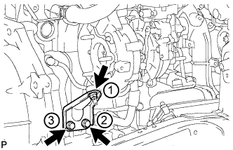
INSTALL INTAKE PIPE STAY
-
Install the intake pipe stay with the bolt.
- Torque:
- 23 N*m { 235 kgf*cm, 17 ft.*lbf }
-
-
INSTALL MANIFOLD STAY WITH VACUUM SWITCHING VALVE
-
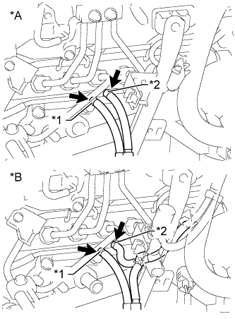
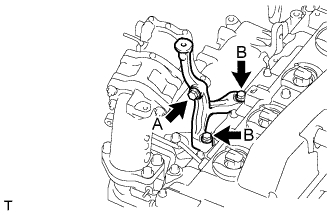
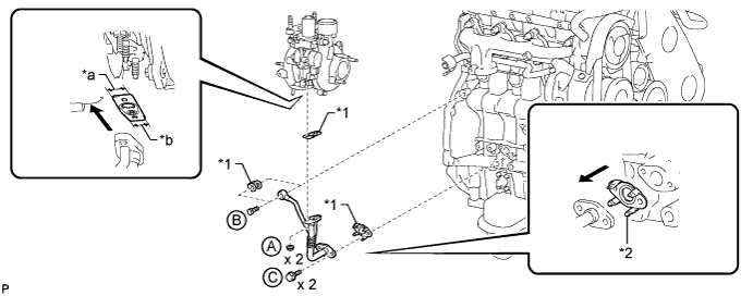
Text in Illustration *A w/o EGR System *B w/ EGR System *1 Blue Mark *2 White Mark Install the manifold stay with vacuum switching valve with the 2 bolts and connect the No. 3 vacuum transmitting hose assembly and No. 4 vacuum transmitting hose assembly.
- Torque:
- 19 N*m { 194 kgf*cm, 14 ft.*lbf }
Note
Make sure the vacuum hose color matches the connection area color.
-
w/ EGR Cooler:
Connect the No. 3 vacuum transmitting hose.
-
Text in Illustration *1 Yellow Mark *2 Pink Mark w/ EGR System:
Connect the No. 2 vacuum transmitting hose and No. 3 vacuum transmitting hose assembly.
Note
-
Make sure the vacuum hose color matches the connection area color.
-
Push on the hose until it reaches the bent part of the pipe.
-
-
Connect the No. 1 vacuum transmitting hose.
-
-
INSTALL GLOW PLUG ASSEMBLY
-
Using a 12 mm socket wrench, install the 4 glow plugs.
- Torque:
- 13 N*m { 133 kgf*cm, 10 ft.*lbf }
-
-
INSTALL NO. 1 INTAKE MANIFOLD INSULATOR
-
Install the No. 1 intake manifold insulator.
-
-
INSTALL NO. 1 GLOW PLUG CONNECTOR
-
Install the glow plug connector with the 4 nuts. Uniformly tighten the nuts.
- Torque:
- 2.2 N*m { 22 kgf*cm, 19 in.*lbf }
-
Install the 4 screw grommets.
-
-
INSTALL WATER OUTLET
-
Install a new gasket and the water outlet with the 2 bolts.
- Torque:
- 19 N*m { 194 kgf*cm, 14 ft.*lbf }
-
-
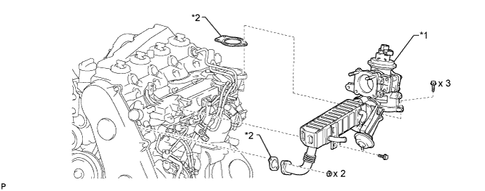
INSTALL NO. 2 EGR HOLE COVER PLATE (w/o EGR System)
-
Install a new gasket and the No. 2 EGR hole cover plate with the 2 nuts.
- Torque:
- 13 N*m { 133 kgf*cm, 10 ft.*lbf }
-
-
INSTALL NO. 2 INTAKE AIR CONNECTOR (w/o EGR System)
-
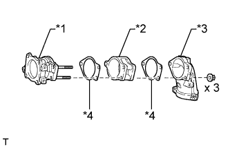
Text in Illustration *1 No. 2 Intake Air Connector *2 No. 1 Intake Air Connector *3 Intake Air Connector *4 Gasket Install the No. 2 intake air connector, No. 1 intake air connector, intake air connector and 2 new gaskets with the 3 nuts as shown in the illustration.
- Torque:
- 20 N*m { 204 kgf*cm, 15 ft.*lbf }
-
-
INSTALL INTAKE AIR CONNECTOR (w/o EGR System)
-
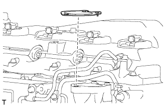
Set a new gasket on the intake manifold.
Note
Make sure the claws of the gasket face the intake manifold as shown in the illustration.
-
Install the intake air connector with the 3 bolts.
- Torque:
- 20 N*m { 204 kgf*cm, 15 ft.*lbf }
Note
Tighten the bolts in the order shown in the illustration.
-
-
INSTALL AIR CONNECTOR STAY (w/o EGR System)
-
Temporarily install the air connector stay with the 3 bolts.
-
Tighten the bolt labeled A.
- Torque:
- 20 N*m { 204 kgf*cm, 15 ft.*lbf }
-
Tighten the 2 bolts labeled B.
- Torque:
- 20 N*m { 204 kgf*cm, 15 ft.*lbf }
-
-
INSTALL INJECTION PIPE (w/o EGR System)
Note
-
When replacing an injector, it is necessary to replace the 4 injection pipes with new ones.
-
Keep the joints of the injection pipe clean.
-
Text in Illustration *1 No. 2 Injection Pipe Temporarily install the No. 1, No. 2 and No. 3 injection pipes with the union nuts.
-
Install the No. 2 and No. 3 injection pipe clamps with the 2 bolts and 2 nuts as shown in the illustration.
- Torque:
- 5.0 N*m { 51 kgf*cm, 44 in.*lbf }
Tech Tips
If the painted mark on the No. 2 injection pipe has disappeared, use the illustration as a reference to install the clamps.
-
*a for Common Rail Side *b for Injector Side Using a 17 mm union nut wrench, tighten the injection pipe union nuts on the common rail side.
- Torque:
- 35 N*m { 357 kgf*cm, 26 ft.*lbf }
Note
Use the formula to calculate special torque values for situations where a union nut wrench is combined with a torque wrench Click here.
-
Using a 17 mm union nut wrench, tighten the injection pipe union nuts on the injector side.
- Torque:
- 35 N*m { 357 kgf*cm, 26 ft.*lbf }
Note
Use the formula to calculate special torque values for situations where a union nut wrench is combined with a torque wrench Click here.
-
-
INSTALL THROTTLE BODY BRACKET (w/o EGR System)
-
Install the throttle body bracket with the 2 bolts.
- Torque:
- 20 N*m { 204 kgf*cm, 15 ft.*lbf }
-
Install the gas filter with gas filter bracket with the bolt.
- Torque:
- 20 N*m { 204 kgf*cm, 15 ft.*lbf }
-
Connect the vacuum hose.
-
-
INSTALL NO. 2 EGR VALVE ASSEMBLY (w/ EGR Cooler)
-
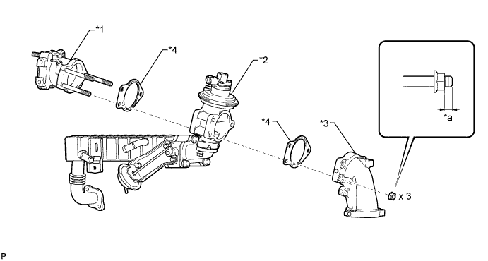
Using a 6 mm hexagon wrench, install the EGR valve adapter, No. 2 EGR valve, EGR cooler, 2 new gaskets, 3 plate washers with the 3 hexagon bolts.
- Torque:
- 28 N*m { 286 kgf*cm, 21 ft.*lbf }
-
Using a 5 mm hexagon wrench, install the bolt labeled A.
- Torque:
- 13 N*m { 133 kgf*cm, 10 ft.*lbf }
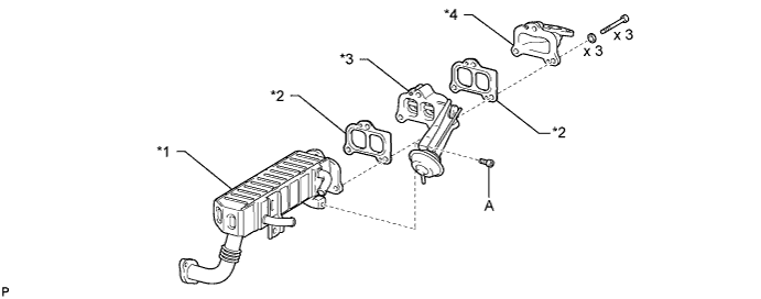
Text in Illustration *1 EGR Cooler with Pipe *2 New Gasket *3 No. 2 EGR Valve *4 EGR Valve Adapter
-
-
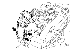
INSTALL EGR COOLER WITH PIPE (w/ EGR System with EGR Cooler)
-
Install a new gasket and the EGR cooler with pipe to the electric EGR control valve and No. 2 EGR valve with the 2 bolts.
- Torque:
- 13 N*m { 133 kgf*cm, 10 ft.*lbf }
Tech Tips
Make sure the claws of the gasket face the electric EGR control valve.
Text in Illustration *1 EGR Cooler with Pipe and No. 2 EGR Valve *2 New Gasket *3 Electric EGR Control Valve - -
-
-
TEMPORARILY INSTALL ELECTRIC EGR CONTROL VALVE ASSEMBLY (w/ EGR System with EGR Cooler)
-
Place a new gasket, the electric EGR control valve, another new gasket and the intake air connector onto the stud bolts of the No. 2 intake air connector and temporarily install the 3 nuts.
Note
Temporarily install the nuts so that 0 to 2 threads of each stud bolt are visible as shown in the illustration.
Text in Illustration *1 No. 2 Intake Air Connector *2 Electric EGR Control Valve *3 Intake Air Connector *4 New Gasket *a 0 to 2 threads - - -
Set a new gasket on the intake manifold.
Tech Tips
Make sure the claws of the gasket face the intake manifold.
-
Temporarily install the intake air connector to the intake manifold with the 3 bolts in the illustration.
-
Temporarily install the EGR cooler with pipe and new gasket to the cylinder head with the bolt and 2 nuts.
Text in Illustration *1 Electric EGR Control Valve *2 New Gasket -
Connect the No. 2 vacuum transmitting hose to the No. 2 EGR valve.
-
-
TIGHTEN ELECTRIC EGR CONTROL VALVE ASSEMBLY (w/ EGR System with EGR Cooler)
-
Tighten the 3 nuts labeled A in the illustration.
- Torque:
- 20 N*m { 204 kgf*cm, 15 ft.*lbf }
-
Tighten the 3 bolts labeled B in the illustration.
- Torque:
- 20 N*m { 204 kgf*cm, 15 ft.*lbf }
Note
Tighten the bolts in the order shown in the illustration.
-
Tighten the bolt labeled C in the illustration.
- Torque:
- 22 N*m { 224 kgf*cm, 16 ft.*lbf }
-
Tighten the 2 nuts labeled D in the illustration.
- Torque:
- 13 N*m { 133 kgf*cm, 10 ft.*lbf }
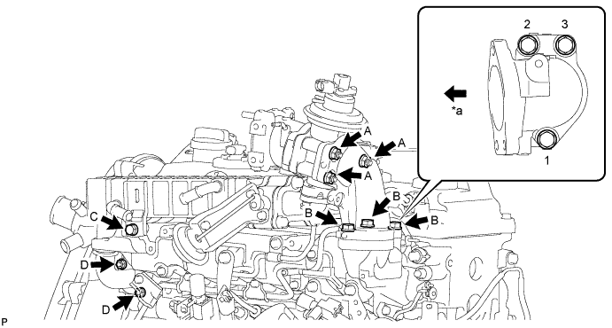
Text in Illustration *a Front - -
-
-
INSTALL NO. 1 EGR PIPE SUB-ASSEMBLY (w/ EGR System without EGR Cooler)
-
Install a new gasket and the No. 1 EGR pipe to the electric EGR control valve with the 2 bolts.
- Torque:
- 13 N*m { 133 kgf*cm, 10 ft.*lbf }
Tech Tips
Make sure the claws of the gasket face the electric EGR control valve.
Text in Illustration *1 Electric EGR Control Valve *2 New Gasket *3 No. 1 EGR Pipe - -
-
-
TEMPORARILY INSTALL ELECTRIC EGR CONTROL VALVE ASSEMBLY (w/ EGR System without EGR Cooler)
-
Place a new gasket, the electric EGR control valve, another new gasket and the intake air connector onto the stud bolts of the No. 2 intake air connector and temporarily install the 3 nuts.
Note
Temporarily install the nuts so that 0 to 2 threads of each stud bolt are visible as shown in the illustration.
Text in Illustration *1 No. 2 Intake Air Connector *2 Electric EGR Control Valve *3 Intake Air Connector *4 New Gasket *a 0 to 2 threads - - -
Set a new gasket on the intake manifold.
Tech Tips
Make sure the claws of the gasket face the intake manifold.
-
Temporarily install the intake air connector to the intake manifold with the 3 bolts in the illustration.
-
Temporarily install the EGR cooler with pipe and new gasket to the cylinder head with the bolt and 2 nuts.
Text in Illustration *1 Electric EGR Control Valve *2 New Gasket -
Connect the No. 2 vacuum transmitting hose to the No. 2 EGR valve.
-
-
TIGHTEN ELECTRIC EGR CONTROL VALVE ASSEMBLY (w/ EGR System without EGR Cooler)
-
Tighten the 3 nuts labeled A in the illustration.
- Torque:
- 20 N*m { 204 kgf*cm, 15 ft.*lbf }
-
Tighten the 3 bolts labeled B in the illustration.
- Torque:
- 20 N*m { 204 kgf*cm, 15 ft.*lbf }
Note
Tighten the bolts in the order shown in the illustration.
-
Tighten the bolt labeled C in the illustration.
- Torque:
- 22 N*m { 224 kgf*cm, 16 ft.*lbf }
-
Tighten the 2 nuts labeled D in the illustration.
- Torque:
- 13 N*m { 133 kgf*cm, 10 ft.*lbf }
Text in Illustration *a Front - -
-
-
INSTALL AIR CONNECTOR STAY (w/ EGR System)
-
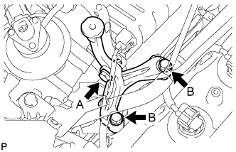
Temporarily install the air connector stay with the 3 bolts.
-
Tighten the bolt labeled A.
- Torque:
- 20 N*m { 204 kgf*cm, 15 ft.*lbf }
-
Tighten the 2 bolts labeled B.
- Torque:
- 20 N*m { 204 kgf*cm, 15 ft.*lbf }
-
-
INSTALL ELECTRIC VACUUM REGULATING VALVE ASSEMBLY (w/ EGR System)
-
Install the E-VRV bracket with the 2 bolts.
- Torque:
- 20 N*m { 204 kgf*cm, 15 ft.*lbf }
-
Install the gas filter and the gas filter bracket with the bolt.
- Torque:
- 20 N*m { 204 kgf*cm, 15 ft.*lbf }
-
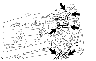
Text in Illustration *1 Yellow Mark *2 Pink Mark Connect the 5 vacuum hoses.
Note
Install the vacuum hoses so that they completely cover the pipes.
-
Connect the 2 connectors to the electric EGR control valve and E-VRV.
-
Attach the wire harness clamp.
-
-
INSTALL EGR VALVE BRACKET (w/ EGR System)
-
Install the EGR valve bracket with the 2 nuts.
- Torque:
- 8.0 N*m { 82 kgf*cm, 71 in.*lbf }
-
-
INSTALL INJECTION PIPE (w/ EGR System)
Note
-
When replacing an injector, it is necessary to replace the 4 injection pipes with new ones.
-
Keep the joints of the injection pipe clean.
-
Text in Illustration *1 No. 2 Injection Pipe Temporarily install the No. 1, No. 2 and No. 3 injection pipes with the union nuts.
-
Install the No. 2 and No. 3 injection pipe clamps with the 2 bolts and 2 nuts as shown in the illustration.
- Torque:
- 5.0 N*m { 51 kgf*cm, 44 in.*lbf }
Tech Tips
If the painted mark on the No. 2 injection pipe has disappeared, use the illustration as a reference to install the clamps.
-
*a for Common Rail Side *b for Injector Side Using a 17 mm union nut wrench, tighten the injection pipe union nuts on the common rail side.
- Torque:
- 35 N*m { 357 kgf*cm, 26 ft.*lbf }
Note
Use the formula to calculate special torque values for situations where a union nut wrench is combined with a torque wrench Click here.
-
Using a 17 mm union nut wrench, tighten the injection pipe union nuts on the injector side.
- Torque:
- 35 N*m { 357 kgf*cm, 26 ft.*lbf }
Note
Use the formula to calculate special torque values for situations where a union nut wrench is combined with a torque wrench Click here.
-
-
CONNECT NO. 4 WATER BY-PASS HOSE (w/ EGR System with EGR Cooler)
-
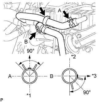
Text in Illustration *1 Lower Side *2 Upper Side *3 LH Side of Vehicle Connect the No. 4 water by-pass hose to the EGR cooler.
Tech Tips
-
The direction of the hose clamp is indicated in the illustration.
-
Insert the outlet hose into the stopper.
-
-
-
CONNECT NO. 3 WATER BY-PASS HOSE (w/ EGR System with EGR Cooler)
-
Connect the No. 3 water by-pass hose to the EGR cooler.
Tech Tips
-
The direction of the hose clamp is indicated in the illustration.
-
Insert the outlet hose into the stopper.
-
-
Install the clamp.
-
-
INSTALL CRANKSHAFT PULLEY
-
Align the keyway of the pulley with the key located on the crankshaft, and then slide the pulley into place to install it.
-
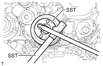
Using SST, install the pulley bolt.
- SST
- 09213-58014
- 09330-00021
- Torque:
- 365 N*m { 3722 kgf*cm, 269 ft.*lbf }
-
-
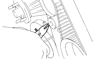
INSTALL NO. 1 TIMING BELT IDLER SUB-ASSEMBLY
-
Using a 10 mm hexagon wrench, install a new washer and the No. 1 timing belt idler with the bolt.
- Torque:
- 35 N*m { 357 kgf*cm, 26 ft.*lbf }
-
Check that the idler pulley moves smoothly.
If the idler pulley does not move smoothly, check the installation condition of the idler and washer.
-
-
INSTALL TIMING BELT
-
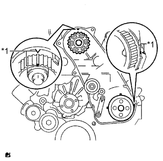
Text in Illustration *1 Timing Mark Check that the timing marks are aligned as shown in the illustration.
Tech Tips
If reusing the timing belt, align the points marked during removal, and install the belt with the arrow pointing in the direction of crankshaft revolution.
Note
-
Make sure that the engine is cold.
-
When turning the crankshaft, the valve heads will hit against the piston. Do not turn the crankshaft more than necessary.
-
-
Install the timing belt to the pump drive shaft pulley, camshaft timing pulley and No. 1 timing belt idler in sequence.
-
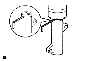
Place the tensioner upright. Then set a press on the top of the tensioner.
Note
-
Do not scratch or deform the rod end.
-
Press in the tensioner rod.
-
Protect the tip of the push rod with a cloth in order to prevent damage.
-
-
Using the press, slowly push in the push rod using 981 to 9807 N (100 to 1000 kgf, 220 to 2205 lbf) of force.
Note
Do not apply a load of over 9807 N (1000 kgf, 2205 lbf) to the push rod.
-
Align the holes of the push rod and housing. Then pass a 1.5 mm hexagon wrench through the holes to fix the push rod in place.
-
Temporarily install the timing belt tensioner with the 2 bolts while pushing the idler pulley toward the timing belt.
-
Tighten the 2 bolts.
- Torque:
- 13 N*m { 133 kgf*cm, 10 ft.*lbf }
Note
Uniformly tighten the 2 bolts.
-
Remove the 1.5 mm hexagon wrench from the tensioner.
-
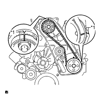
Text in Illustration *1 Timing Mark Turn the crankshaft clockwise 720° and check that the timing marks are aligned as shown in the illustration.
-
-
INSTALL NO. 1 TIMING BELT COVER
-
Install the timing belt cover and 6 washers with the 6 bolts.
- Torque:
- 6.0 N*m { 61 kgf*cm, 53 in.*lbf }
-
-
INSTALL CRANKSHAFT POSITION SENSOR
-
Attach the clamp and install the crankshaft position sensor with the bolt.
- Torque:
- 8.5 N*m { 87 kgf*cm, 75 in.*lbf }
-
-
INSTALL CAMSHAFT POSITION SENSOR
-
Install the camshaft position sensor with the bolt.
- Torque:
- 8.5 N*m { 87 kgf*cm, 75 in.*lbf }
-
-
INSTALL ENGINE COOLANT TEMPERATURE SENSOR
-
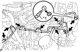
Install a new gasket to the engine coolant temperature sensor.
-
Install the engine coolant temperature sensor.
- Torque:
- 20 N*m { 200 kgf*cm, 14 ft.*lbf }
-
Connect the engine coolant temperature sensor connector.
-
-
INSTALL VANE PUMP ASSEMBLY
-
Install a new O-ring and the vane pump with the 2 nuts.
- Torque:
- 41 N*m { 418 kgf*cm, 30 ft.*lbf }
-
-
INSTALL VACUUM PUMP ASSEMBLY
-
Install 2 new O-rings to the vacuum pump.
-
Install the vacuum pump with the 2 nuts.
- Torque:
- 21 N*m { 210 kgf*cm, 15 ft.*lbf }
-
-
INSTALL TIMING GEAR COVER INSULATOR
-
Install the timing gear cover insulator with the bolt.
- Torque:
- 8.0 N*m { 82 kgf*cm, 71 in.*lbf }
-
-
INSTALL ENGINE OIL LEVEL SENSOR
-
Install a new gasket and the engine oil level sensor with the 4 bolts.
- Torque:
- 8.0 N*m { 82 kgf*cm, 71 ft.*lbf }
-
-
INSTALL NO. 2 WATER BY-PASS PIPE SUB-ASSEMBLY
-
Install the No. 2 water by-pass pipe with the 2 bolts and 2 nuts.
- Torque:
- 8.0 N*m { 82 kgf*cm, 71 ft.*lbf }
-
Connect the 2 hoses.
-
-
INSTALL THERMOSTAT
-
Install a new gasket to the thermostat.
Note
When installing the gasket to the thermostat, be careful not to deform the gasket. Make sure that the gasket is properly installed to the thermostat, as shown in the illustration.
-
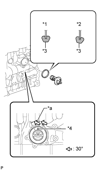
Text in Illustration *1 CORRECT *2 INCORRECT *3 Gasket *4 Jiggle Valve *a Upward Install the thermostat to the cylinder block with the jiggle valve facing straight upward.
Tech Tips
The jiggle valve may be set within 30° of either side of the prescribed position.
-
-
INSTALL WATER INLET
-
Install the water inlet with the 3 bolts.
- Torque:
- 13 N*m { 133 kgf*cm, 10 ft.*lbf }
-
-
INSTALL COMPRESSOR ELBOW STAY
-
Install the compressor elbow stay with the 2 bolts.
- Torque:
- 19 N*m { 194 kgf*cm, 14 ft.*lbf }
-
-
INSTALL NO. 2 CYLINDER HEAD COVER SUB-ASSEMBLY
-
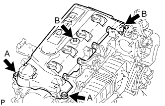
Install the No. 2 cylinder head cover with the 4 bolts.
- Torque:
- for bolt A
- 18 N*m { 184 kgf*cm, 13 ft.*lbf }
- for bolt B
- 8.0 N*m { 82 kgf*cm, 71 in.*lbf }
-
-
INSTALL EXHAUST MANIFOLD WITH TURBOCHARGER
-
Temporarily install a new gasket and the turbocharger with 3 new nuts.
Tech Tips
It is easier to install the turbo oil inlet pipe if the 3 nuts are only loosely installed.
-
Set a new gasket on the engine and install the exhaust manifold with turbocharger, 8 collars and 8 plate washers with 8 new nuts.
- Torque:
- 40 N*m { 408 kgf*cm, 30 ft.*lbf }
Note
Install the collars so that the side with the smaller external diameter faces the exhaust manifold.
-
Temporarily install the turbo oil inlet pipe.
Tech Tips
Before installing the turbo oil inlet pipe, clean it.
-
Install a new gasket and the turbo oil inlet pipe with the 2 nuts, but only loosely install the nuts.
Note
The notch (narrow part) of the gasket must face the engine.
-
Install a new gasket and the turbo oil inlet pipe with the 2 bolts, but only loosely install the bolts.
Note
The claws of the gasket must face the pipe.
-
Install a new gasket and the turbo oil inlet pipe with the union bolt, but only loosely install the union bolt.
Text in Illustration *1 New Gasket *2 Claw *a Wide *b Narrow 
Outside - - -
Temporarily install the turbocharger stay with the 2 bolts and nut.
-
-
Tighten the 3 nuts of the turbocharger.
- Torque:
- 52 N*m { 530 kgf*cm, 38 ft.*lbf }
-
Tighten the 2 nuts labeled A.
- Torque:
- 13 N*m { 133 kgf*cm, 10 ft.*lbf }
-
Tighten the union bolt labeled B.
- Torque:
- 26 N*m { 265 kgf*cm, 19 ft.*lbf }
-
Tighten the 2 bolts labeled C.
- Torque:
- 12 N*m { 122 kgf*cm, 9 ft.*lbf }
-
Tighten the 2 bolts and nut of the turbocharger stay in the order shown in the illustration.
- Torque:
- 38 N*m { 387 kgf*cm, 28 ft.*lbf }
-
-
INSTALL TURBINE OUTLET ELBOW
-
Install a new gasket and the turbine outlet elbow with the 3 nuts.
- Torque:
- 39 N*m { 398 kgf*cm, 29 ft.*lbf }
-
-
CONNECT NO. 1 TURBO WATER HOSE
-
Connect the No. 1 turbo water hose to the No. 1 turbo water pipe.
-
-
INSTALL NO. 1 EXHAUST MANIFOLD HEAT INSULATOR
-
Temporarily install the No. 1 exhaust manifold heat insulator with the bolt.
-
-
INSTALL NO. 1 TURBO INSULATOR
-
Temporarily install the No. 1 turbo insulator with the 2 bolts.
-
Tighten the bolt of the No. 1 exhaust manifold heat insulator and the 2 bolts of the No. 1 turbo insulator.
- Torque:
- 12 N*m { 122 kgf*cm, 9 ft.*lbf }
-
-
INSTALL COMPRESSOR INLET ELBOW
-
Install a new gasket and the compressor inlet elbow with the 2 nuts.
- Torque:
- 19 N*m { 194 kgf*cm, 14 ft.*lbf }
-
Connect the No. 2 turbo water hose and No. 3 turbo water hose.
-
Connect the 2 connectors and attach the wire harness clamp.
-
Install the wire harness bracket with the bolt.
- Torque:
- 8.0 N*m { 82 kgf*cm, 71 in.*lbf }
-
Attach the 3 wire harness clamps.
-
-
INSTALL ENGINE OIL LEVEL DIPSTICK GUIDE
-
Install a new O-ring to the engine oil level dipstick guide.
-
Apply a small amount of clean engine oil to the O-ring.
-
Install the engine oil level dipstick guide with the 2 bolts.
- Torque:
- 8.0 N*m { 82 kgf*cm, 71 in.*lbf }
-
Install the engine oil level dipstick.
-
-
INSTALL VENTILATION PIPE
-
Connect the 2 ventilation hoses and install the ventilation pipe to the cylinder head cover with the bolt.
- Torque:
- 20 N*m { 204 kgf*cm, 15 ft.*lbf }
-
-
INSTALL NO. 1 COMPRESSOR MOUNTING BRACKET
-
Install the No. 1 compressor mounting bracket with the 5 bolts.
- Torque:
- 21 N*m { 214 kgf*cm, 15 ft.*lbf }
-
-
INSTALL GENERATOR BRACKET
-
Install the generator bracket with the bolts.
- Torque:
- 21 N*m { 214 kgf*cm, 15 ft.*lbf }
-
-
INSTALL GENERATOR ASSEMBLY
-
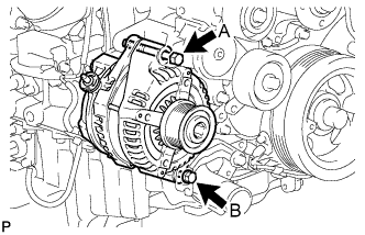
Install the generator with the 2 bolts.
- Torque:
- for bolt A
- 62 N*m { 632 kgf*cm, 46 ft.*lbf }
- for bolt B
- 21 N*m { 214 kgf*cm, 15 ft.*lbf }
-