ENGINE UNIT (w/o DPF) REASSEMBLY

-
INSTALL REAR CRANKSHAFT OIL SEAL
-
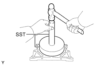
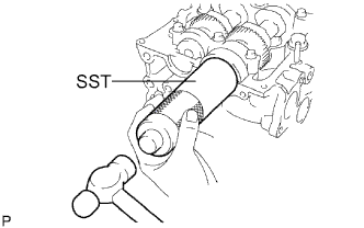
Using SST and a hammer, tap in a new oil seal until its surface is flush with the rear oil seal retainer edge.
- SST
- 09518-36030
- 09950-70010 ( 09951-07100 )
-
Apply MP grease to the lip of the oil seal.
-
-
INSTALL SUPPLY PUMP OIL SEAL
-
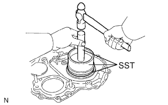
Using SST and a hammer, tap in a new oil seal until its surface is flush with the timing gear cover edge.
- SST
- 09223-15020
- 09502-12010
- 09950-70010 ( 09951-07100 )
-
Apply MP grease to the lip of the oil seal.
-
-
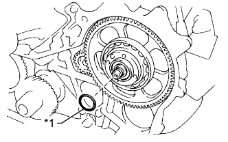
INSTALL FRONT CRANKSHAFT OIL SEAL
-
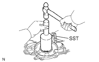
Using SST and a hammer, tap in a new oil seal until its surface is flush with the timing gear cover edge.
- SST
- 09214-76011
-
Apply MP grease to the lip of the oil seal.
-
-
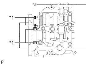
INSTALL REAR ENGINE OIL SEAL RETAINER
-
Remove any old seal packing (FIPG material) from the oil pan and cylinder block.
-
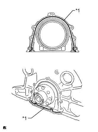
Text in Illustration *1 Seal Packing Apply seal packing to the places shown in the illustration.
Seal packing Toyota Genuine Seal Packing Black, Three Bond 1207B or equivalent Standard seal diameter 4 mm (0.157 in.) Note
After applying seal packing, install the rear engine oil seal retainer within 3 minutes and tighten the bolts within 15 minutes.
-
Install the retainer with the 5 bolts. Alternately tighten the 5 bolts in several passes.
- Torque:
- 13 N*m { 133 kgf*cm, 10 ft.*lbf }
-
-
INSTALL NO. 2 BALANCESHAFT DRIVEN GEAR
-
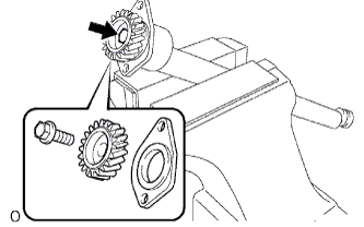
Mount the balanceshaft between aluminum plates in a vise.
Note
Be careful not to damage the balanceshaft.
-
Align the balanceshaft knock pin with the knock pin hole. Then install the balanceshaft thrust washer and balanceshaft driven gear.
-
Install the bolt.
- Torque:
- 36 N*m { 367 kgf*cm, 27 ft.*lbf }
-
-
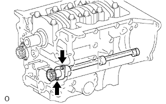
INSTALL NO. 2 BALANCESHAFT SUB-ASSEMBLY
-
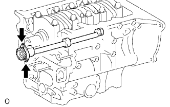
Install the balanceshaft with the 2 bolts.
- Torque:
- 13 N*m { 133 kgf*cm, 10 ft.*lbf }
-
-
INSTALL NO. 1 BALANCESHAFT DRIVEN GEAR
-
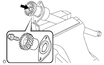
Mount the balanceshaft between aluminum plates in a vise.
Note
Be careful not to damage the balanceshaft.
-
Align the balanceshaft knock pin with the knock pin hole. Then install the balanceshaft thrust washer and balanceshaft driven gear.
-
Install the bolt.
- Torque:
- 36 N*m { 367 kgf*cm, 27 ft.*lbf }
-
-
INSTALL NO. 1 BALANCESHAFT SUB-ASSEMBLY
-
Install the balanceshaft with the 2 bolts.
- Torque:
- 13 N*m { 133 kgf*cm, 10 ft.*lbf }
-
-
INSTALL TIMING GEAR CASE ASSEMBLY
-
Remove any old seal packing (FIPG material).
-
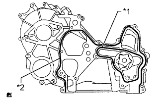
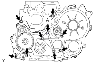
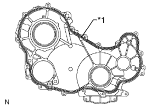
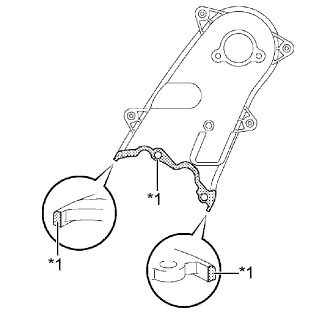
Text in Illustration *1 New Gasket *2 Seal Packing Apply seal packing to the timing gear case as shown in the illustration.
Seal packing Toyota Genuine Seal Packing Black, Three Bond 1207B or equivalent Standard seal diameter 5 mm (0.197 in.) Note
After applying seal packing, install the timing gear case assembly within 3 minutes and tighten the bolts within 15 minutes.
-
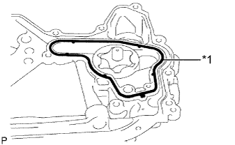
Text in Illustration *1 New Gasket Install a new gasket to the groove of the timing gear case.
-
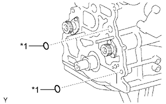
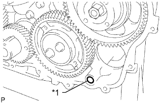
Text in Illustration *1 New O-Ring Install 2 new O-rings to the cylinder block.
-

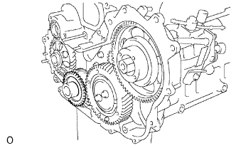
Align the "2" marks of the balanceshaft driven gear No. 1 and oil pump drive gear.
-
Align the mark on the oil pump drive gear with the mark on the timing gear case.
-
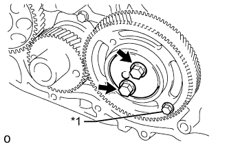
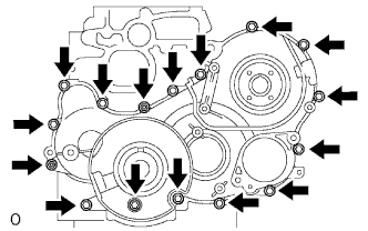
Install the timing gear case with the union bolt and 8 bolts.
- Torque:
- for union bolt (A)
- 16 N*m { 163 kgf*cm, 12 ft.*lbf }
- for bolt
- 13 N*m { 133 kgf*cm, 10 ft.*lbf }
-
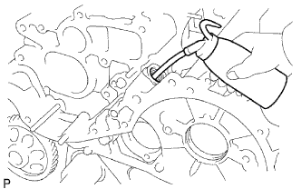
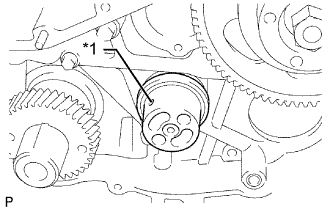
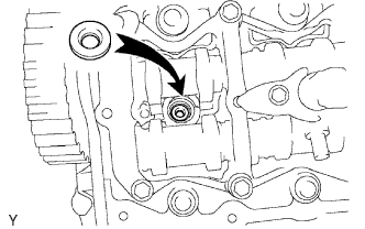
Remove the screw plug and gasket.
-
Pour approximately 50 cc (3.05 cu. in.) of engine oil into the oil pump.
-
Install a new gasket and the screw plug.
- Torque:
- 44 N*m { 449 kgf*cm, 32 ft.*lbf }
-
-
INSTALL OIL PAN SUB-ASSEMBLY
-
Remove any old seal packing (FIPG material) and be careful not to drop any oil on the contact surfaces of the cylinder block, rear oil seal retainer and oil pan.
-
Install a new gasket to the cylinder block.
-
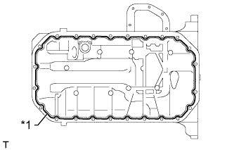
Text in Illustration *1 Seal Packing Apply seal packing in a continuous line as shown in the illustration.
Seal packing Toyota Genuine Seal Packing Black, Three Bond 1207B or equivalent Standard seal diameter 4 mm (0.157 in.) Note
-
Remove any oil from the contact surface.
-
Install the oil pan within 3 minutes after applying seal packing.
-
Do not start the engine for at least 2 hours after installation.
-
-
Install the oil pan with the 22 bolts and 2 nuts.
- Torque:
- 15 N*m { 148 kgf*cm, 11 ft.*lbf }
-
-
INSTALL OIL STRAINER SUB-ASSEMBLY
-
Install a new gasket and the oil strainer with the 2 nuts.
- Torque:
- 8.0 N*m { 82 kgf*cm, 71 in.*lbf }
-
-
INSTALL NO. 2 OIL PAN SUB-ASSEMBLY
-
Remove any old seal packing (FIPG material).
-
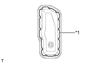
Text in Illustration *1 Seal Packing Apply seal packing to the No. 2 oil pan as shown in the illustration.
Seal packing Toyota Genuine Seal Packing Black, Three Bond 1207B or equivalent Standard seal diameter 4 mm (0.157 in.) Note
-
Remove any oil from the contact surface.
-
Install the No. 2 oil pan within 3 minutes after applying seal packing.
-
Do not start the engine for at least 2 hours after installation.
-
-
Install the No. 2 oil pan with the 13 bolts and 2 nuts.
- Torque:
- 9.0 N*m { 92 kgf*cm, 80 in.*lbf }
-
-
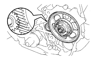
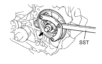
INSTALL CRANKSHAFT TIMING GEAR

-
Position the crankshaft timing gear with timing mark 1 facing forward.
-
Align the key groove of the crankshaft timing gear with the set key on the crankshaft.
-
Using SST and a hammer, tap on the timing gear to install it.
- SST
- 09223-00010
-
-
INSTALL INJECTION GEAR
-
Install a new O-ring and the supply pump with the 2 nuts.
- Torque:
- 21 N*m { 214 kgf*cm, 15 ft.*lbf }
-
Temporarily install the injection gear with the nut.
Tech Tips
Fit the key (protrusion) of the supply pump into the key slot of the injection gear.
-
Align the "3" marks of the balanceshaft driven gear No. 2 and injection gear.
-
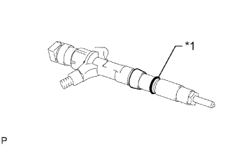
Text in Illustration *1 New O-Ring Install a new O-ring to the injection gear.
-
Install the injection gear set nut.
-
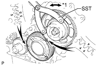
Using SST, tighten the nut.
- SST
- 09960-10010 ( 09962-01000, 09963-01000 )
- Torque:
- 64 N*m { 653 kgf*cm, 47 ft.*lbf }
-
-
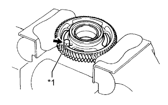
INSTALL NO. 2 IDLE SUB GEAR
-
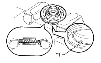
Text in Illustration *1 Cutout Mark Mount the No. 1 idle gear in a vise.
Tech Tips
Make sure the cutout mark of the idle gear faces down.
Note
Be careful not to damage the gear.
-
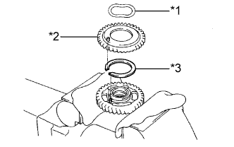
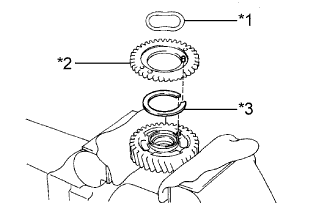
Text in Illustration *1 Wave Washer *2 No. 2 Idle Sub Gear *3 Idle Gear Spring Install the idle gear spring.
-
Install the No. 2 idle sub gear.
-
Install the wave washer.
Tech Tips
Fit the pins on the gears between the spring ends.
-
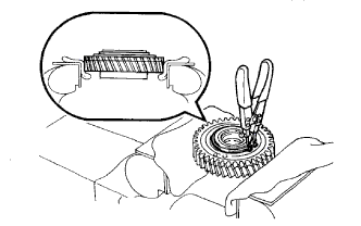
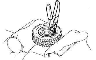
Using snap ring pliers, install the shaft snap ring.
-
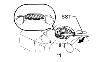
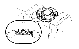
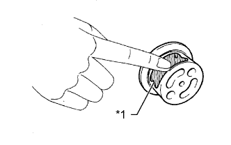
Text in Illustration *1 Service Bolt Using SST, align the holes of the No. 1 idle gear and No. 2 idle sub gear by turning the No. 2 idle sub gear clockwise and install a service bolt.
- SST
- 09960-10010 ( 09962-01000, 09963-00700 )
-
Remove the No. 1 idle gear from the vise and turn it upside down.
-
-
INSTALL NO. 1 IDLE SUB GEAR
-
Text in Illustration *1 Upward Mount the No. 1 idle gear and No. 2 idle sub gear in a vise.
Note
Be careful not to damage the gears.
-
Text in Illustration *1 Service Bolt Remove the service bolt.
-
Text in Illustration *1 Wave Washer *2 No. 1 Idle Sub Gear *3 Idle Gear Spring Install the idle gear spring.
-
Install the No. 1 idle sub gear.
-
Install the wave washer.
Tech Tips
Fit the pins on the gears between the spring ends.
-
Using a snap ring pliers, install the shaft snap ring.
-

Text in Illustration *1 Service Bolt *2 Upward Using SST, align the holes of the No. 1 idler gear and No. 1 idle sub gear by turning the No. 1 idle sub gear clockwise, and install the service bolt.
- SST
- 09960-10010 ( 09962-01000, 09963-00600 )
-
-
INSTALL NO. 1 IDLE GEAR SHAFT
-
Text in Illustration *1 Engine Oil Apply a coat of engine oil to the No. 1 idle gear shaft.
-
Text in Illustration *1 Oil Hole Install the gear shaft as shown in the illustration.
-
-
INSTALL NO. 1 IDLE GEAR
-
Text in Illustration *1 Turn Align the "5" timing marks of the idle gear and crankshaft timing gear.
-
Using SST, turn the injection gear and align the "4" timing marks of the idle gear and injection gear, and then mesh the gears.
- SST
- 09960-10010 ( 09962-01000, 09963-00700 )
-
Text in Illustration *1 Service Bolt Position the thrust plate with the protrusion facing forward.
-
Align the bolt holes and install the thrust plate with the 2 bolts.
- Torque:
- 50 N*m { 510 kgf*cm, 37 ft.*lbf }
-
Remove the service bolt.
-
-
INSTALL NO. 1 CRANKSHAFT POSITION SENSOR PLATE
-
Align the key groove of the sensor plate with the set key.
-
Install the sensor plate with the cupped side facing outward.
-
-
INSTALL TIMING GEAR COVER
-
Remove any old seal packing (FIPG material).
-
Text in Illustration *1 Seal Packing Apply seal packing to the timing gear cover as shown in the illustration.
Seal packing Toyota Genuine Seal Packing Black, Three Bond 1207B or equivalent Standard seal diameter 4 mm (0.157 in.) Note
After applying seal packing, install the timing gear cover within 3 minutes and tighten the bolts within 15 minutes.
-
Text in Illustration *1 New O-Ring Install a new O-ring to the timing gear case.
-
Install the timing gear cover with the 14 bolts and 2 nuts.
- Torque:
- 13 N*m { 133 kgf*cm, 10 ft.*lbf }
-
-
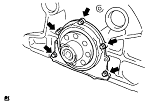
INSTALL WATER PUMP ASSEMBLY
-
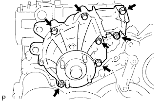
Install a new gasket and the water pump with the 5 bolts and 2 nuts.
- Torque:
- 13 N*m { 133 kgf*cm, 10 ft.*lbf }
-
-
INSTALL CYLINDER HEAD GASKET
-
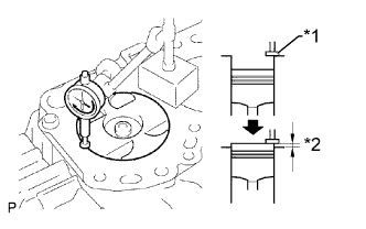
Text in Illustration *1 Measuring Tip *2 Protrusion Find where the piston head protrudes most by slowly turning the crankshaft clockwise and counterclockwise.
-
Text in Illustration *1 Measuring Point Measure the piston protrusion of each cylinder at 2 points as shown in the illustration.
-
For the piston protrusion value of each cylinder, use the average of the 2 measurements of each cylinder.
Piston protrusion 0.005 to 0.255 mm (0.000197 to 0.0100 in.) Tech Tips
After installing the piston and connecting rod assembly, if the protrusion is not as specified, remove the piston and connecting rod assembly and reinstall them.
-
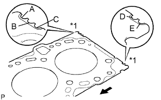
Text in Illustration *1 Cutout Mark 
Front Select a new cylinder head gasket.
Tech Tips
New cylinder head gaskets are available in 5 sizes, and are marked A, B, C, D or E.
New Cylinder Head Gasket Thickness Mark Specified Condition A 0.80 to 0.90 mm (0.0315 to 0.0354 in.) B 0.85 to 0.95 mm (0.0335 to 0.0374 in.) C 0.90 to 1.00 mm (0.0354 to 0.0394 in.) D 0.95 to 1.05 mm (0.0374 to 0.0413 in.) E 1.00 to 1.10 mm (0.0394 to 0.0433 in.)
-
Select the largest piston protrusion value from the measurements made. Then select a new gasket to the table below.
Gasket Size Item Specified Condition Piston protrusion 0.005 to 0.054 mm (0.000197 to 0.00213 in.) 0.055 to 0.104 mm (0.00217 to 0.00409 in.) 0.105 to 0.154 mm (0.00413 to 0.00606 in.) 0.155 to 0.204 mm (0.00610 to 0.00803 in.) 0.205 to 0.255 mm (0.00807 to 0.0100 in.) Use gasket A B C D E
-
-
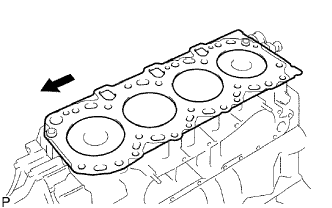
Place the cylinder head gasket on the cylinder block.
Text in Illustration Front Note
Make sure the gasket is installed facing the proper direction.
-
-
INSTALL CYLINDER HEAD SUB-ASSEMBLY
Tech Tips
-
The cylinder head bolts are tightened in 3 progressive steps.
-
If any bolt is broken or deformed, replace it Click here.
-
Place the cylinder head on the cylinder head gasket.
-
Apply a light coat of engine oil on the threads and under the heads of the cylinder head bolts.
-
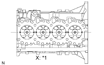
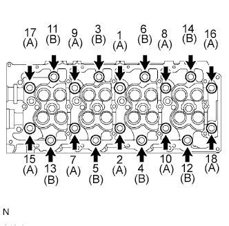
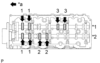
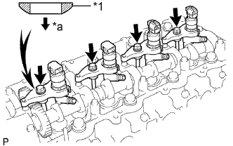
Install the 18 washers with the 18 cylinder head bolts, and uniformly tighten the bolts, in several passes in the sequence shown in the illustration.
- Torque:
- 85 N*m { 867 kgf*cm, 63 ft.*lbf }
Bolt length A 110 mm (4.33 in.) Bolt length B 167 mm (6.57 in.) If any of the cylinder head bolts does not meet the torque specification, replace it.
-
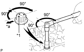
*1 Painted Mark *a Front Mark the front of each cylinder head bolt with paint.
-
Further tighten the cylinder head bolts by 90° in the sequence shown in the illustration above.
-
Tighten the cylinder head bolts by an additional 90°.
-
Check that the painted marks are now facing rearward.
-
-
INSTALL VALVE LIFTER
-
Install the valve lifter.
-
Check that the valve lifter rotates smoothly by hand.
-
-
INSTALL CAMSHAFT
-
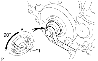
Text in Illustration *1 Key Using the crankshaft pulley bolt, set the No. 1 cylinder to 90° BTDC/compression.
Tech Tips
Set the No. 1 cylinder to 90° BTDC/compression to prevent the top of the piston from hitting against the valve head.
-
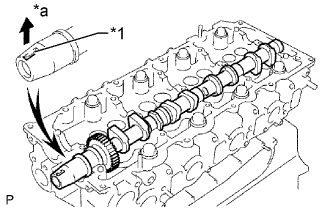
Install the camshaft.
-
Apply MP grease to the thrust portion of the camshaft.
-
Place the camshaft on the cylinder head with the key groove facing upward.
Text in Illustration *1 Key Groove *a Upward -
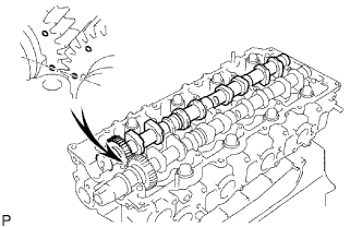
Align the timing marks (1 dot mark) of the camshaft drive and driven main gears, and set the No. 2 camshaft in place.
-
-
Remove any old seal packing (FIPG material) from the camshaft bearing cap.
-
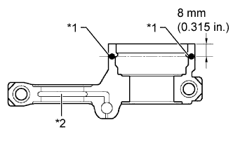
Apply seal packing to the specified areas shown in the illustration.
Text in Illustration *1 Seal Packing *2 Oil Passage Seal packing Toyota Genuine Seal Packing Black, Three Bond 1207B or equivalent Standard seal diameter 4 mm (0.157 in.) Note
-
Do not allow seal packing to contact the oil passage of the bearing cap.
-
After applying seal packing, install the camshaft bearing caps within 3 minutes and tighten the bolts within 15 minutes.
-
Do not start the engine for at least 2 hours after installation.
-
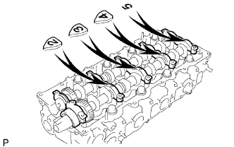
Install the 5 bearing caps to their proper locations.
-
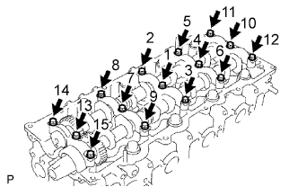
Apply a light coat of engine oil to the threads and under the heads of the bearing cap bolts.
-
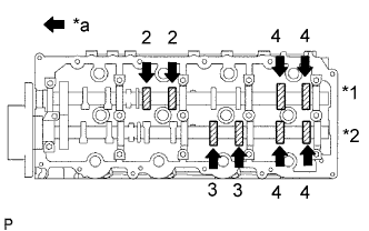
Install and uniformly tighten the 15 bearing cap bolts in several passes in the sequence shown in the illustration.
- Torque:
- 19 N*m { 194 kgf*cm, 14 ft.*lbf }
-
-
Install a new camshaft oil seal.
-
Apply MP grease to the lip of a new oil seal.
-
Using SST and a hammer, tap in the oil seal until its surface is flush with the surfaces of the camshaft bearing cap and cylinder head.
- SST
- 09608-06041
-
-
-
INSPECT VALVE CLEARANCE
-
Text in Illustration *1 Exhaust *2 Intake *a Front Check only the valves indicated.
-
Using a feeler gauge, measure the clearance between the valve lifter and camshaft.
Standard Valve Clearance (Cold) Item Specified Condition Intake 0.2 to 0.3 mm (0.00787 to 0.0118 in.) Exhaust 0.35 to 0.45 mm (0.0138 to 0.0177 in.) Write down any valve clearance measurements that are not within the specified range. These measurements will be used later to determine the size of the adjustment lifter to be installed.
-
-
Turn the crankshaft 360° to set the No. 4 cylinder to TDC/compression.
-
Text in Illustration *1 Exhaust *2 Intake *a Front Check only the valves indicated.
-
Using a feeler gauge, measure the clearance between the valve lifter and camshaft.
Standard Valve Clearance (Cold) Item Specified Condition Intake 0.2 to 0.3 mm (0.00787 to 0.0118 in.) Exhaust 0.35 to 0.45 mm (0.0138 to 0.0177 in.) Write down valve clearance measurements that are not within the specified range. These measurements will be used later to determine the size of the adjustment lifter to be installed.
-
-
-
ADJUST VALVE CLEARANCE
-
w/ DPF:
Remove the camshafts Click here.
-
w/o DPF:
Remove the camshafts Click here.
-
Remove the valve lifters.
-
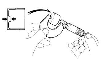
Using a micrometer, measure the thickness of the removed lifter.
-
Calculate the thickness of a new lifter so that the valve clearance is within the specified range.
A B C New lifter thickness Used lifter thickness Measured valve clearance New lifter thickness Intake: A = B + (C - 0.25 mm (0.00984 in.)) Exhaust: A = B + (C - 0.40 mm (0.0157 in.)) -
Select a new lifter with a thickness as close as possible to the calculated values.
Tech Tips
Valve lifters are available in 35 sizes in increments of 0.02 mm (0.000787 in.), from 5.06 mm (0.199 in.) to 5.74 mm (0.226 in.).
-
Install the selected valve lifter.
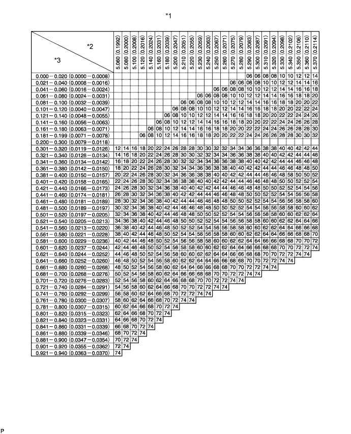
Text in Illustration *1 Valve Lifter Selection Chart (Intake) *2 Installed lifter thickness mm (in.) *3 Measured clearance mm (in.) - - 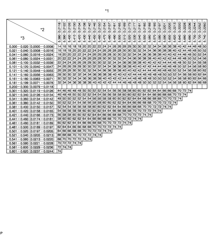
Text in Illustration *1 Valve Lifter Selection Chart (Intake) *2 Installed lifter thickness mm (in.) *3 Measured clearance mm (in.) - - Standard intake valve clearance (Cold) 0.2 to 0.3 mm (0.00787 to 0.0118 in.) EXAMPLE A 5.25 mm (0.207 in.) lifter is installed, and the measured clearance is 0.4 mm (0.0157 in.). Replace the 5.25 mm (0.207 in.) lifter with a No. 40 lifter. New Lifter Thickness Lifter No. Specified Condition Lifter No. Specified Condition Lifter No. Specified Condition 06 5.06 mm (0.1992 in.) 30 5.30 mm (0.2087 in.) 54 5.54 mm (0.2181 in.) 08 5.08 mm (0.2000 in.) 32 5.32 mm (0.2094 in.) 56 5.56 mm (0.2189 in.) 10 5.10 mm (0.2008 in.) 34 5.34 mm (0.2102 in.) 58 5.58 mm (0.2197 in.) 12 5.12 mm (0.2016 in.) 36 5.36 mm (0.2110 in.) 60 5.60 mm (0.2205 in.) 14 5.14 mm (0.2024 in.) 38 5.38 mm (0.2118 in.) 62 5.62 mm (0.2213 in.) 16 5.16 mm (0.2031 in.) 40 5.40 mm (0.2126 in.) 64 5.64 mm (0.2220 in.) 18 5.18 mm (0.2039 in.) 42 5.42 mm (0.2134 in.) 66 5.66 mm (0.2228 in.) 20 5.20 mm (0.2047 in.) 44 5.44 mm (0.2142 in.) 68 5.68 mm (0.2236 in.) 22 5.22 mm (0.2055 in.) 46 5.46 mm (0.2150 in.) 70 5.70 mm (0.2244 in.) 24 5.24 mm (0.2063 in.) 48 5.48 mm (0.2157 in.) 72 5.72 mm (0.2252 in.) 26 5.26 mm (0.2071 in.) 50 5.50 mm (0.2165 in.) 74 5.74 mm (0.2260 in.) 28 5.28 mm (0.2079 in.) 52 5.52 mm (0.2173 in.) - - 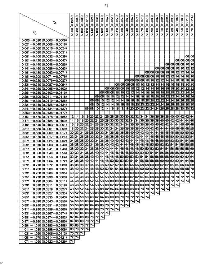
Text in Illustration *1 Valve Lifter Selection Chart (Exhaust) *2 Installed lifter thickness mm (in.) *3 Measured clearance mm (in.) - - 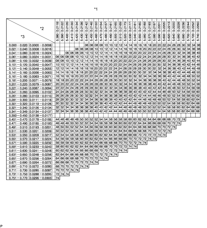
Text in Illustration *1 Valve Lifter Selection Chart (Exhaust) *2 Installed lifter thickness mm (in.) *3 Measured clearance mm (in.) - - Standard exhaust valve clearance (Cold) 0.35 to 0.45 mm (0.0138 to 0.0177 in.) EXAMPLE A 5.34 mm (0.210 in.) lifter is installed, and the measured clearance is 0.48 mm (0.0189 in.). Replace the 5.34 mm (0.210 in.) lifter with a No. 42 lifter. New Lifter Thickness Lifter No. Specified Condition Lifter No. Specified Condition Lifter No. Specified Condition 06 5.06 mm (0.1992 in.) 30 5.30 mm (0.2087 in.) 54 5.54 mm (0.2181 in.) 08 5.08 mm (0.2000 in.) 32 5.32 mm (0.2094 in.) 56 5.56 mm (0.2189 in.) 10 5.10 mm (0.2008 in.) 34 5.34 mm (0.2102 in.) 58 5.58 mm (0.2197 in.) 12 5.12 mm (0.2016 in.) 36 5.36 mm (0.2110 in.) 60 5.60 mm (0.2205 in.) 14 5.14 mm (0.2024 in.) 38 5.38 mm (0.2118 in.) 62 5.62 mm (0.2213 in.) 16 5.16 mm (0.2031 in.) 40 5.40 mm (0.2126 in.) 64 5.64 mm (0.2220 in.) 18 5.18 mm (0.2039 in.) 42 5.42 mm (0.2134 in.) 66 5.66 mm (0.2228 in.) 20 5.20 mm (0.2047 in.) 44 5.44 mm (0.2142 in.) 68 5.68 mm (0.2236 in.) 22 5.22 mm (0.2055 in.) 46 5.46 mm (0.2150 in.) 70 5.70 mm (0.2244 in.) 24 5.24 mm (0.2063 in.) 48 5.48 mm (0.2157 in.) 72 5.72 mm (0.2252 in.) 26 5.26 mm (0.2071 in.) 50 5.50 mm (0.2165 in.) 74 5.74 mm (0.2260 in.) 28 5.28 mm (0.2079 in.) 52 5.52 mm (0.2173 in.) - - -
w/ DPF:
Install the camshafts Click here.
-
w/o DPF:
Install the camshafts Click here.
-
-
INSTALL CYLINDER BLOCK INSULATOR
-
Install the cylinder block insulator to the cylinder head.
-
-
INSTALL NO. 2 TIMING BELT COVER
-
Text in Illustration *1 Seal Packing Apply seal packing (FIPG) to the specified areas shown in the illustration.
Seal packing Toyota Genuine Seal Packing Black, Three Bond 1207B or equivalent Note
After applying seal packing, install the No. 2 timing belt cover within 3 minutes and tighten the bolts and nut within 15 minutes.
-
Install the No. 2 timing belt cover with the 4 bolts and nut.
- Torque:
- 10 N*m { 102 kgf*cm, 7 ft.*lbf }
-
-
INSTALL CAMSHAFT TIMING PULLEY
-
Install the camshaft timing pulley.
-
Install the bolt of the camshaft timing pulley while holding the camshaft with a wrench.
- Torque:
- 98 N*m { 1000 kgf*cm, 72 ft.*lbf }
-
-
INSTALL INJECTOR ASSEMBLY
Note
Be sure to install the injector, No. 1 nozzle holder clamp, washer and bolt in their original positions.
-
Install 4 new injection nozzle seats to the cylinder head.
-
Apply a small amount of clean engine oil to 4 new O-rings.
-
Text in Illustration *1 New O-Ring Install an O-ring to each injector as shown in the illustration.
-
Insert the 4 injectors into the cylinder head.
Note
-
Insert the injector until it touches the injection nozzle seat surface.
-
After installing the injector to the cylinder head, the O-ring may prevent the injector from fully seating. If so, pull out the injector and reinstall it.
-
Always return an injector to the same place it was removed from.
-
-
For an injector that has been replaced with a new injector, register the injector compensation code Click here.
-
Text in Illustration *1 Washer *a Downward Temporarily install 4 new washers and the 4 No. 1 nozzle holder clamps with the 4 bolts.
Tech Tips
Apply a small amount of engine oil to the threads and under the heads of the clamp bolts.
-
Temporarily install the 4 injection pipes with the union nuts.
Tech Tips
To position the injectors, loosely tighten the union nut.
-
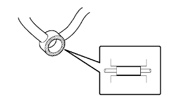
Check the nozzle leakage pipe. Check that there are no scratches or dents on the 5 union seal surfaces.
If scratches or dents are present, replace the nozzle leakage pipe.
-
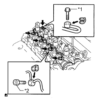
Text in Illustration *1 Union Bolt *2 Hollow Screw Set the leakage pipe and 5 new gaskets in place.
-
Apply a small amount of oil to the 4 injector hollow screws and union bolt.
-
Temporarily install the leakage pipe with the 4 injector hollow screws and union bolt.
-
Tighten the 4 holder clamp bolts.
- Torque:
- 22 N*m { 220 kgf*cm, 16 ft.*lbf }
-
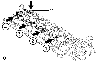
Text in Illustration *1 Union Bolt Tighten the 4 hollow screws in order from 1 to 4.
- Torque:
- 16 N*m { 163 kgf*cm, 12 ft.*lbf }
Note
If a hollow screw is accidentally tightened beyond the torque specification, it must be replaced.
-
Tighten the union bolt.
- Torque:
- 13 N*m { 127 kgf*cm, 9 ft.*lbf }
Note
If the union bolt is accidentally tightened beyond the torque specification, it must be replaced.
-
Remove the 4 injection pipes.
-
-
INSPECT FOR FUEL LEAK
-
Check that there are no leaks from the nozzle leakage pipe connection.
-
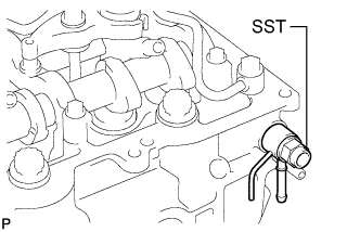
Install the gasket and No. 2 nozzle leakage pipe to the cylinder head with SST (check valve).
Part No. 23762-27010 (No. 2 nozzle leakage pipe) - SST
- 09280-00010
- Torque:
- 21 N*m { 214 kgf*cm, 15 ft.*lbf }
-
Apply a small amount of soapy water (or other fluid for detecting fuel leakage) on the nozzle leakage pipe connection.
-
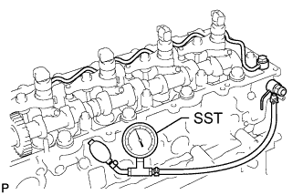
Install SST (turbocharger pressure gauge) to the fuel return side of the leakage pipe, maintain 100 kPa (1.0 kgf/cm2, 15 psi) of pressure for 60 seconds and check that no bubbles form.
- SST
- 09992-00242
-
After checking for fuel leaks, wipe off the soapy water from the leakage pipe connection.
-
Remove SST, the No. 2 nozzle leakage pipe and gasket.
Note
Never reinstall the disassembled union bolt to the engine.
-
-
-
INSTALL CYLINDER HEAD COVER SUB-ASSEMBLY
-
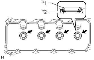
Text in Illustration *1 No. 3 Cylinder Head Cover Gasket *2 Cylinder Head Cover Install 4 new No. 3 cylinder head cover gaskets to the cylinder head cover in the directions shown in the illustration.
Note
-
Do not install the No. 3 cylinder head cover gaskets at an angle.
-
Check that there is no foreign matter at the installation location of the No. 3 cylinder head cover gaskets.
-
-
Remove any old seal packing (FIPG material) from the cylinder head.
-
Text in Illustration *1 Seal Packing Apply seal packing to the areas shown in the illustration.
Seal packing Toyota Genuine Seal Packing Black, Three Bond 1207B or equivalent Note
-
Remove any oil from the contact surface.
-
Install the cylinder head cover within 3 minutes after applying seal packing.
-
Do not start the engine for at least 2 hours after installation.
-
-
Install a new gasket and the cylinder head cover with the 10 bolts and 2 nuts.
- Torque:
- 9.0 N*m { 92 kgf*cm, 80 in.*lbf }
-
-
INSTALL NOZZLE HOLDER SEAL
-
Install 4 new nozzle holder seals.
-
-
INSTALL OIL FILLER CAP SUB-ASSEMBLY