ENGINE UNIT (w/ DPF) REMOVAL

Note
-
When replacing the injectors (including shuffling the injectors between the cylinders), common rail or cylinder head, it is necessary to replace the injection pipes with new ones.
-
When replacing the fuel supply pump, common rail, cylinder block, cylinder head, cylinder head gasket or timing gear case, it is necessary to replace the fuel inlet pipe with a new one.
-
REMOVE GENERATOR ASSEMBLY
-
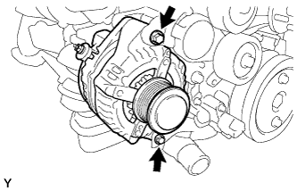
Remove the 2 bolts and generator.
-
-
REMOVE GENERATOR BRACKET
-
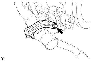
Remove the bolt and generator bracket.
-
-
REMOVE IDLE PULLEY ASSEMBLY (w/ Air Conditioning System)
-
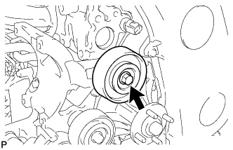
Remove the bolt, pulley plate, idle pulley and spacer.
-
-
REMOVE NO. 2 IDLE PULLEY ASSEMBLY (w/ Air Conditioning System)
-
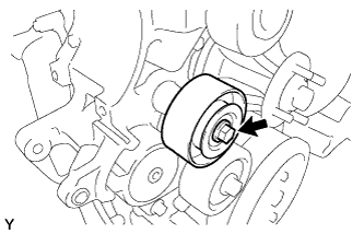
Remove the bolt, pulley plate, No. 2 idle pulley and spacer.
-
-
REMOVE NO. 1 COMPRESSOR MOUNTING BRACKET
-
Remove the 5 bolts and No. 1 compressor mounting bracket.
-
-
REMOVE NO. 1 FUEL PIPE
-
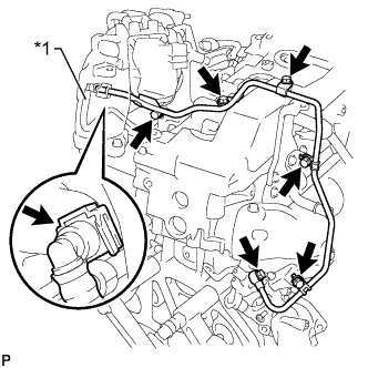
Text in Illustration *1 No. 2 Fuel Pipe Disconnect the No. 2 fuel pipe Click here.
-
Remove the 4 bolts, union bolt, gasket and No. 1 fuel pipe.
-
-
REMOVE NO. 2 EXHAUST MANIFOLD HEAT INSULATOR
-
Remove the 2 bolts and No. 2 exhaust manifold heat insulator.
-
-
REMOVE TURBINE OUTLET ELBOW STAY
-
Remove the 2 bolts and turbine outlet elbow stay.
-
-
REMOVE NO. 2 TURBINE OUTLET ELBOW
-
Remove the 3 nuts, No. 2 turbine outlet elbow and gasket.
-
-
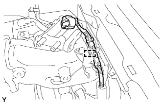
REMOVE FUEL PIPE CLAMP
-
Remove the bolt and fuel pipe clamp.
-
-
REMOVE NO. 11 WATER BY-PASS HOSE
-
Disconnect the exhaust fuel addition injector connector.
-
Remove the No. 11 water by-pass hose.
-
-
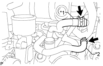
REMOVE TURBINE OUTLET ELBOW
-
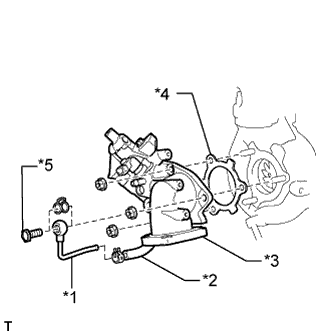
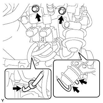
Text in Illustration *1 No. 4 Water By-pass Pipe *2 No. 12 Water By-pass Hose *3 Turbine Outlet Elbow *4 Gasket *5 Union Bolt Remove the union bolt and gasket from the turbine outlet elbow.
-
Disconnect the No. 4 water by-pass pipe from the No. 12 water by-pass hose.
-
Remove the 3 nuts, turbine outlet elbow and gasket.
-
-
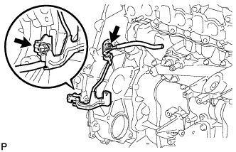
REMOVE VENTILATION PIPE
-
Remove the bolt and disconnect the 2 ventilation hoses and ventilation pipe.
-
-
REMOVE NO. 1 TURBO INSULATOR
-
Remove the 2 bolts and No. 1 turbo insulator.
-
-
REMOVE NO. 1 EXHAUST MANIFOLD HEAT INSULATOR
-
Remove the 2 bolts and No. 1 exhaust manifold heat insulator.
-
-
DISCONNECT ENGINE OIL LEVEL DIPSTICK GUIDE SUB-ASSEMBLY
-
Remove the bolt.
-
Disconnect the engine oil level dipstick guide.
-
-
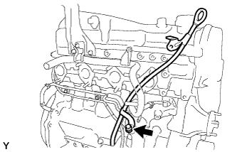
DISCONNECT NO. 1 TURBO WATER HOSE
-
Text in Illustration *1 No. 1 Turbo Water Hose *2 No. 3 Turbo Water Hose Disconnect the No. 1 turbo water hose from the No. 2 water by-pass pipe.
-
-
DISCONNECT NO. 3 TURBO WATER HOSE
-
Disconnect the No. 3 turbo water hose from the No. 2 water by-pass pipe.
-
-
REMOVE TURBOCHARGER STAY
-
Remove the 2 bolts, nut and turbocharger stay.
-
-
REMOVE WIRE HARNESS CLAMP BRACKET
-
Remove the bolt and wire harness clamp bracket.
-
-
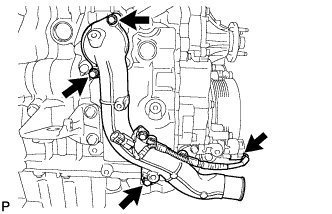
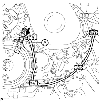
REMOVE TURBO OIL INLET PIPE SUB-ASSEMBLY
-
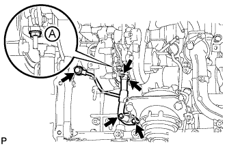
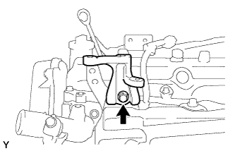
Remove the 2 bolts, 2 nuts, union bolt, turbo oil inlet pipe and 3 gaskets.
Note
Do not loosen the nut labeled A in the illustration.
-
-
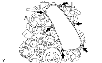
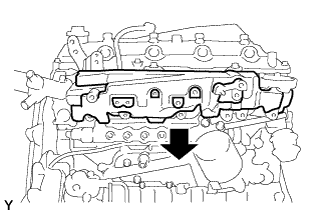
REMOVE EXHAUST MANIFOLD WITH TURBOCHARGER
-
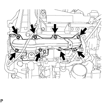
Remove the 8 nuts and 8 plate washers from the exhaust manifold with turbocharger.
-
Remove the exhaust manifold with turbocharger and gasket.
-
-
REMOVE ENGINE OIL LEVEL DIPSTICK GUIDE SUB-ASSEMBLY
-
Remove the bolt and engine oil level dipstick guide.
-
-
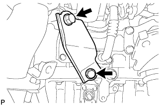
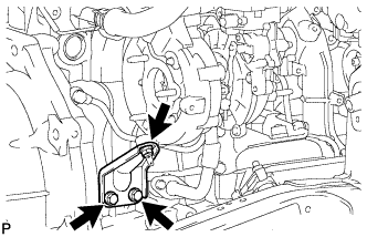
REMOVE COMPRESSOR ELBOW STAY
-
Remove the 3 bolts and compressor elbow stay.
-
-
REMOVE NO. 5 WATER BY-PASS PIPE SUB-ASSEMBLY
-
Disconnect the 3 hoses.
-
Remove the 2 bolts, nut and No. 5 water by-pass pipe.
-
-
REMOVE NO. 2 WATER BY-PASS PIPE SUB-ASSEMBLY
-
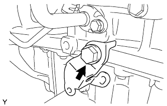
Remove the bolt, nut and No. 2 water by-pass pipe.
-
-
REMOVE NO. 2 ENGINE COVER BRACKET
-
Remove the 2 bolts and No. 2 engine cover bracket.
-
-
REMOVE NO. 3 VACUUM TRANSMITTING PIPE SUB-ASSEMBLY
-
Disconnect the 2 vacuum hoses.
-
Remove the bolt and No. 3 vacuum transmitting pipe.
-
-
REMOVE NO. 1 VACUUM PIPE
-
Remove the bolt and No. 1 vacuum pipe.
-
-
REMOVE NO. 2 CYLINDER BLOCK INSULATOR
-
Remove the No. 2 cylinder block insulator from the front No. 1 engine mounting bracket RH.
-
-
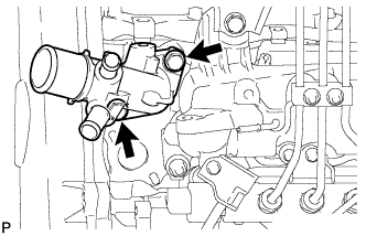
REMOVE WATER INLET
-
Disconnect the connector and remove the 3 bolts and water inlet.
-
-
REMOVE THERMOSTAT
-
Remove the thermostat.
-
Remove the gasket from the thermostat.
-
-
REMOVE NO. 3 CYLINDER BLOCK INSULATOR
-
Detach the clip and remove the No. 3 cylinder block insulator.
-
-
REMOVE ENGINE OIL LEVEL SENSOR
-
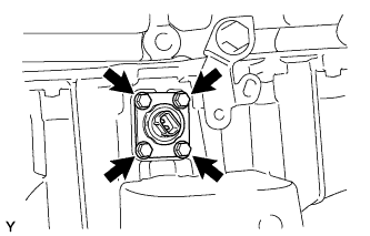
Remove the 4 bolts and engine oil level sensor.
-
Cut away part of the gasket and remove the gasket from the engine oil level sensor.
Tech Tips
Remove only the outer part of the gasket.
-
-
REMOVE VACUUM PUMP ASSEMBLY
-
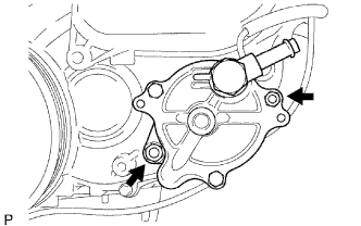
Remove the 2 nuts, vacuum pump and 2 O-rings.
-
-
REMOVE VANE PUMP ASSEMBLY
-
Remove the 2 nuts, vane pump and O-ring.
-
-
REMOVE ENGINE COOLANT TEMPERATURE SENSOR
-
Disconnect the engine coolant temperature sensor connector.
-
Remove the engine coolant temperature sensor.
-
Remove the gasket from the engine coolant temperature sensor.
-
-
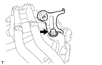
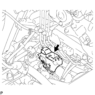
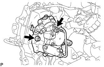
REMOVE OIL PRESSURE SWITCHING VALVE ASSEMBLY
-
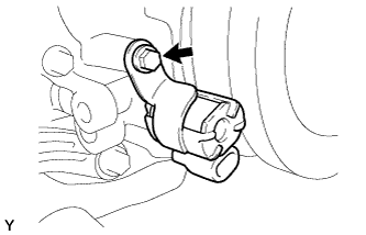
Remove the bolt and oil pressure switching valve.
-
-
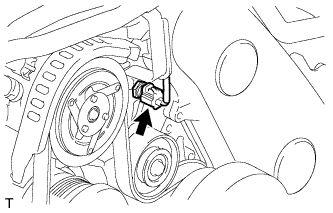
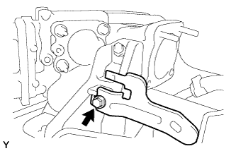
REMOVE CAMSHAFT POSITION SENSOR
-
Remove the bolt and camshaft position sensor.
-
-
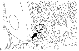
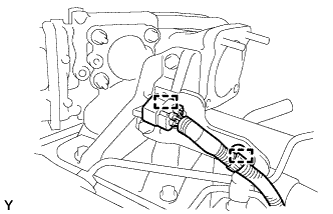
REMOVE CRANKSHAFT POSITION SENSOR
-
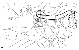
Disconnect the crankshaft position sensor connector.
-
Remove the clamp labeled A in the illustration.
Note
-
Make sure that no portion of the clamp labeled A remains in the clamp installation hole. If there is any portion of the clamp remaining, remove it.
-
Do not reuse the clamp labeled A.
-
-
Detach the 3 wire harness clamps and remove the bolt and crankshaft position sensor.
-
-
REMOVE NO. 1 TIMING BELT COVER
-
Remove the 6 bolts, 6 washers and timing belt cover.
-
-
REMOVE TIMING BELT
-
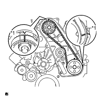
Text in Illustration *1 Timing Mark Turn the crankshaft clockwise and align the timing marks as shown in the illustration.
Tech Tips
If reusing the timing belt, place matchmarks on the timing belt so that it can be installed exactly as before.
-
Uniformly loosen and remove the 2 bolts and No. 1 timing belt tensioner.
-
Remove the timing belt.
Tech Tips
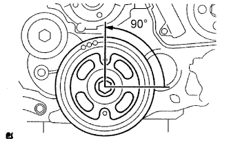
-
If turning the camshaft while the timing belt is removed, turn the crankshaft 90° counterclockwise as shown in the illustration.
-
When installing the timing belt, turn the camshaft to align the timing marks and then turn the crankshaft clockwise to align the timing marks.
-
-
-
REMOVE NO. 1 TIMING BELT IDLER SUB-ASSEMBLY
Note
When inspecting the No. 1 timing belt idler, do not remove it unless absolutely necessary.
-
Using a 10 mm hexagon wrench, remove the bolt, No. 1 timing belt idler and washer.
-
-
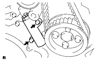
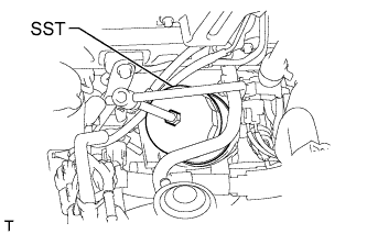
REMOVE CRANKSHAFT PULLEY
-
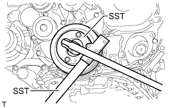
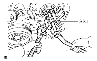
Using SST, hold the crankshaft pulley and loosen the pulley bolt.
- SST
- 09213-58014
- 09330-00021
-
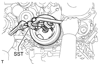
Using SST, remove the pulley bolt and crankshaft pulley.
- SST
- 09950-50013 ( 09951-05010, 09952-05010, 09953-05020, 09954-05021 )
-
-
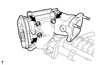
REMOVE DIESEL THROTTLE BODY ASSEMBLY
-
Disconnect the throttle control motor connector.
-
Remove the 2 bolts, 2 nuts, diesel throttle body and gasket.
-
-
REMOVE MANIFOLD ABSOLUTE PRESSURE SENSOR
-
Disconnect the manifold absolute pressure sensor connector and vacuum hose.
-
Remove the bolt and manifold absolute pressure sensor.
-
-
REMOVE EMISSION CONTROL VALVE BRACKET
-
Remove the bolt and emission control valve bracket.
-
-
REMOVE THROTTLE BODY BRACKET
-
Remove the 3 bolts and throttle body bracket.
-
-
REMOVE NO. 1 GAS FILTER
-
Disconnect the vacuum hose and remove the No. 1 gas filter from the gas filter bracket.
-
-
REMOVE GAS FILTER BRACKET
-
Detach the clamp and disconnect the wire harness.
-
Remove the bolt and gas filter bracket.
-
-
REMOVE NO. 2 CYLINDER HEAD COVER SUB-ASSEMBLY
-
Remove the 4 bolts and No. 2 cylinder head cover.
-
-
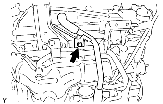
REMOVE NO. 1 VACUUM TRANSMITTING PIPE
-
Disconnect the vacuum hose from the intake manifold.
-
Remove the bolt and No. 1 vacuum transmitting pipe.
-
-
REMOVE MANIFOLD STAY WITH VACUUM SWITCHING VALVE
-
Disconnect the 3 vacuum switching valve connectors.
-
Disconnect the No. 1 vacuum transmitting hose.
-
Disconnect the 2 No. 2 vacuum transmitting hoses from the No. 2 EGR valve.
-
Disconnect the No. 1 vacuum transmitting hose and No. 4 vacuum transmitting hose.
-
Remove the 2 bolts and manifold stay with vacuum switching valve.
-
-
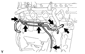
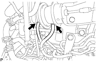
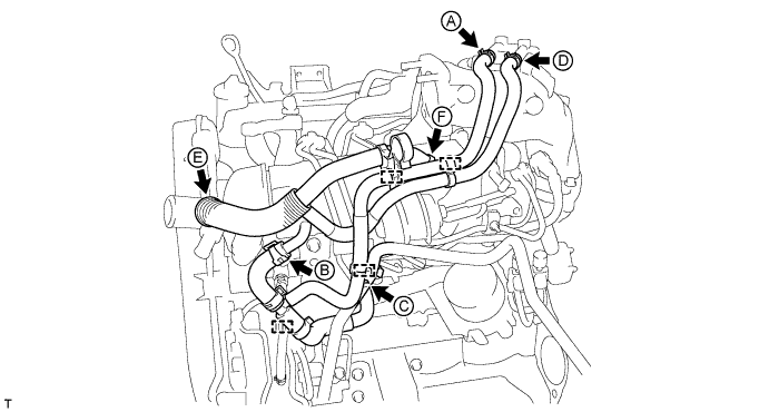
REMOVE WATER BY-PASS HOSE
-
Detach the 4 water by-pass hose clamps.
-
Disconnect the No. 7 water by-pass hose labeled A in the illustration.
-
Disconnect the No. 4 water by-pass hose labeled B in the illustration.
-
Disconnect the No. 3 water by-pass hose labeled C in the illustration.
-
Disconnect the No. 8 water by-pass hose labeled D in the illustration.
-
Disconnect the No. 6 water by-pass hose labeled E in the illustration.
-
Disconnect the No. 5 water by-pass hose labeled F in the illustration.
-
-
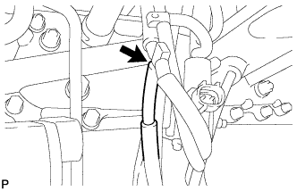
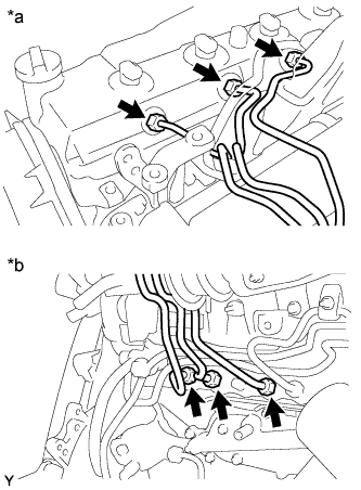
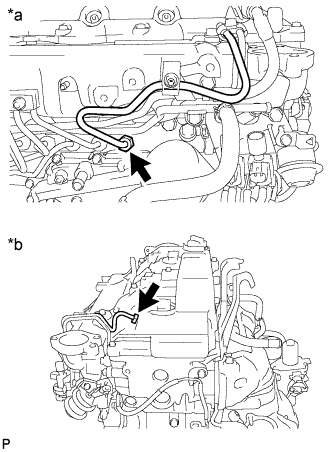
REMOVE FUEL INLET PIPE SUB-ASSEMBLY
-
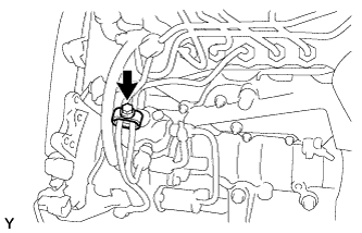
Remove the bolt and No. 2 injection pipe clamp.
-
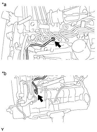
Text in Illustration *a Common Rail Side *b Fuel Supply Pump Side Using a 17 mm union nut wrench, loosen the union nuts and remove the fuel inlet pipe.
-
-
REMOVE WIRING HARNESS CLAMP BRACKET
-
Disconnect the glow plug connector.
-
Detach the 2 wire harness clamps and disconnect the glow plug connector from the wiring harness clamp bracket.
-
Remove the bolt and wiring harness clamp bracket.
-
-
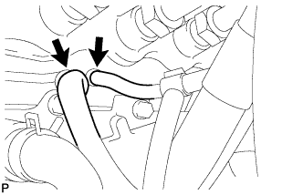
REMOVE NO. 1, NO. 2 AND NO. 3 INJECTION PIPE SUB-ASSEMBLY
Note
-
After removing the injection pipe, cover the outlets on the common rail with tape to keep out foreign matter.
-
After removing the injection pipe, put it in a plastic bag to prevent foreign matter from contaminating its injector inlet.
-
Remove the 2 nuts and No. 3 injection pipe clamp.
-
Remove the 2 bolts and 2 No. 2 injection pipe clamps.
-
Text in Illustration *a Injector Side *b Common Rail Side Using a 17 mm union nut wrench, loosen the union nuts and remove the No. 1, No. 2 and No. 3 injection pipes.
-
-
REMOVE AIR CONNECTOR STAY
-
Remove the 3 bolts and air connector stay.
-
-
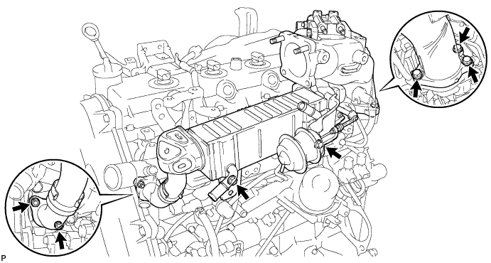
REMOVE ELECTRIC EGR CONTROL VALVE ASSEMBLY WITH NO. 2 EGR VALVE AND EGR COOLER
-
Remove the 2 nuts, the 5 bolts and the electric EGR control valve with No. 2 EGR valve and EGR cooler.
-
Remove the 2 gaskets from the cylinder head and intake manifold.
-
-
REMOVE ELECTRIC EGR CONTROL VALVE ASSEMBLY
-
Remove the 2 nuts, bolt and intake air connector together with the electric EGR control valve.
-
Remove the electric EGR control valve and 2 gaskets from the intake air connector.
-
-
REMOVE EGR VALVE ADAPTER
-
Using a 6 mm hexagon wrench, remove the 3 hexagon bolts, 3 plate washers, EGR valve adapter and gasket.
-
-
REMOVE NO. 2 EGR VALVE ASSEMBLY
-
Remove the bolt, No. 2 EGR valve and gasket.
-
-
REMOVE EGR COOLER INSULATOR
-
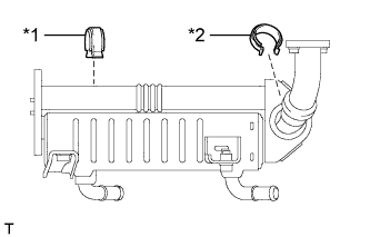
Text in Illustration *1 No. 2 EGR Cooler Insulator *2 No. 1 EGR Cooler Insulator Remove the 2 EGR cooler insulators from the EGR cooler.
-
-
REMOVE NO. 4 INJECTION PIPE SUB-ASSEMBLY
-
Remove the bolt, nut and 2 No. 2 injection pipe clamps.
-
Text in Illustration *a Common Rail Side *b Injector Side Using a 17 mm union nut wrench, loosen the union nuts and remove the No. 4 injection pipe.
-
-
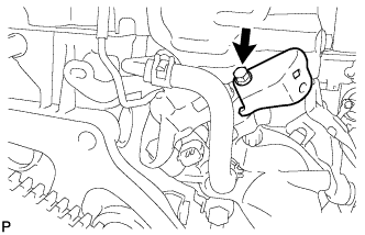
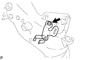
REMOVE NO. 2 FUEL PIPE
-
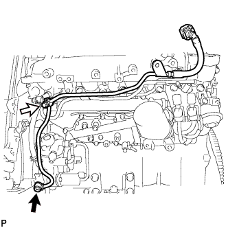
Using a 6 mm hexagon wrench, remove the union bolt and gasket.
Text in Illustration 
Union Bolt 
Fuel Check Valve -
Remove the fuel check valve, gasket and No. 2 fuel pipe.
-
-
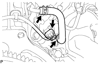
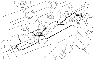
REMOVE NO. 3 NOZZLE LEAKAGE PIPE
-
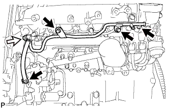
Disconnect the 2 fuel hoses.
Text in Illustration Fuel Check Valve -
Remove the 2 bolts.
-
Remove the fuel check valve, gasket and No. 3 nozzle leakage pipe.
-
-
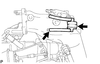
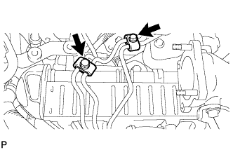
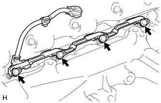
REMOVE NO. 2 NOZZLE LEAKAGE PIPE ASSEMBLY
-
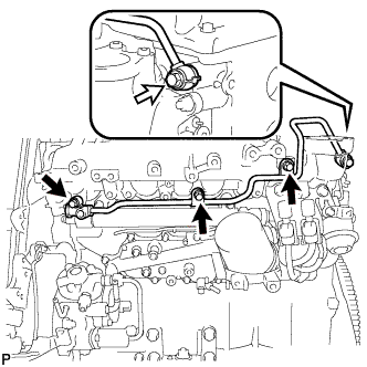
Remove the 3 bolts.
Text in Illustration Union Bolt -
Remove the union bolt, gasket and No. 2 nozzle leakage pipe.
-
-
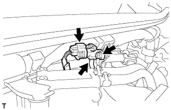
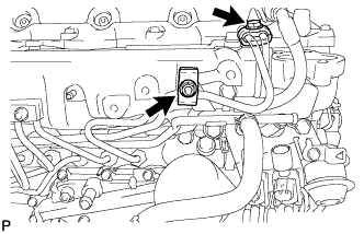
REMOVE VACUUM CONTROL VALVE SET
-
Disconnect the 2 vacuum switching valve connectors.
-
Disconnect the 3 vacuum hoses, and then remove the 2 bolts and vacuum control valve set.
-
-
REMOVE INTAKE PIPE STAY
-
Remove the bolt and intake pipe stay.
-
-
REMOVE INTAKE MANIFOLD INSULATOR
-
Remove the intake manifold insulator.
-
-
REMOVE INTAKE MANIFOLD
-
Detach the sensor wire connector clamp from the intake manifold.
-
Remove the 2 nuts, 4 bolts, intake manifold and gasket.
-
-
REMOVE NO. 1 GLOW PLUG CONNECTOR
-
Disconnect the No. 1 glow plug connector from the wire harness.
-
Remove the 4 screw grommets.
-

Remove the 4 nuts and No. 1 glow plug connector.
-
-
REMOVE NO. 1 INTAKE MANIFOLD INSULATOR
-
REMOVE GLOW PLUG ASSEMBLY
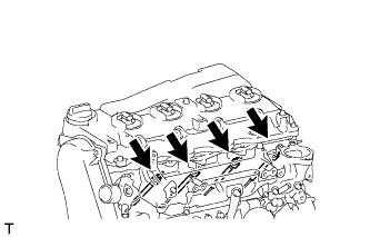
-
Using a 12 mm deep socket wrench, remove the 4 glow plugs.
-
-
REMOVE OIL FILTER SUB-ASSEMBLY
-
Using SST, remove the oil filter.
- SST
- 09228-07501
-
-
REMOVE COMMON RAIL ASSEMBLY
-
Disconnect the pressure discharge valve connector.
-
Remove the 2 bolts and common rail.
Note
Do not remove the pressure discharge valve or fuel pressure sensor.
-
-
REMOVE NO. 2 INTAKE MANIFOLD INSULATOR
-
Remove the No. 2 intake manifold insulator.
-
-
REMOVE INJECTION PUMP INSULATOR
-
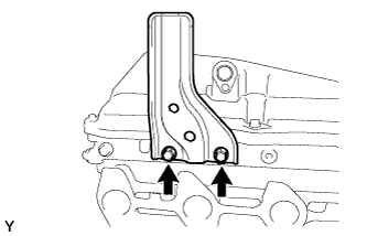
REMOVE NO. 1 INJECTION PUMP PROTECTOR
-
Remove the 2 bolts and No. 1 injection pump protector.
-
-
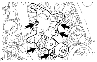
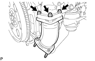
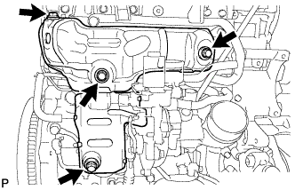
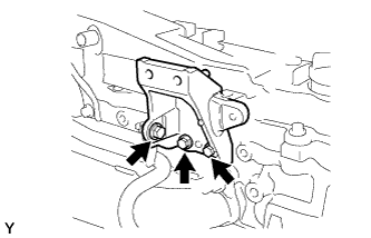
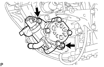
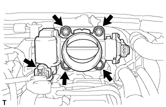
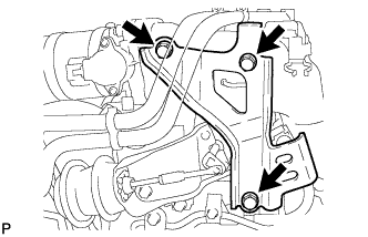
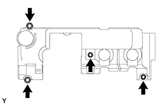
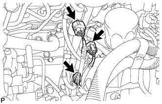
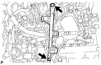
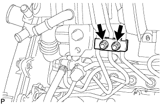
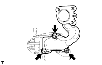
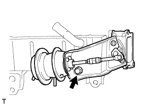
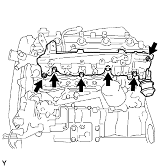
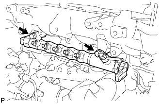
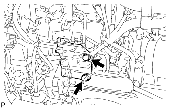
REMOVE FUEL SUPPLY PUMP ASSEMBLY
-
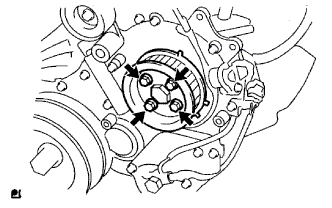
Remove the 4 bolts indicated by the arrows in the illustration.
-
Remove the No. 2 camshaft timing pulley flange and pump drive shaft pulley.
-
Remove the set nut and O-ring while holding the crankshaft pulley using SST.
- SST
- 09213-58014
- 09330-00021
-
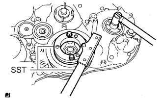
Loosen the 2 nuts.
-
Using SST, disconnect the fuel supply pump from the injection gear.
- SST
- 09950-50013 ( 09951-05010, 09952-05010, 09953-05020, 09954-05021 )
Note
Apply lubricant to the threads and tip of SST (center bolt) before using it.
-
Remove the 2 nuts and fuel supply pump.
Note
-
Do not hold or carry the fuel supply pump by the pipe.
-
The fuel supply pump must be kept horizontal.
-
-
Remove the O-ring.
-
-
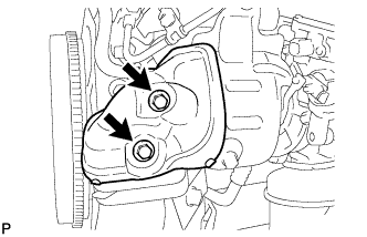
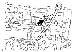
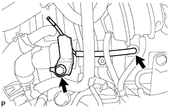
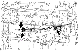
REMOVE WATER OUTLET
-
Remove the 2 bolts, gasket and water outlet.
-
-
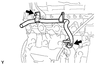
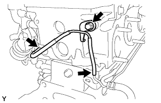
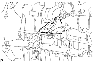
REMOVE NO. 2 VACUUM TRANSMITTING PIPE SUB-ASSEMBLY
-
Disconnect the vacuum hose.
-
Remove the 2 nuts and No. 2 vacuum transmitting pipe.
-
-
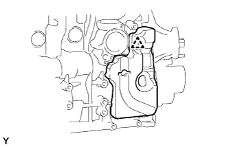
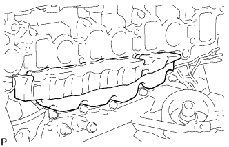
REMOVE OIL COOLER COVER SUB-ASSEMBLY
-
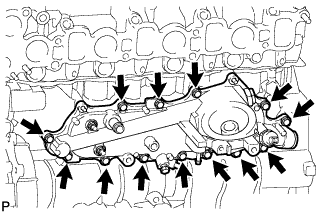
Remove the 13 bolts and oil cooler cover.
-
-
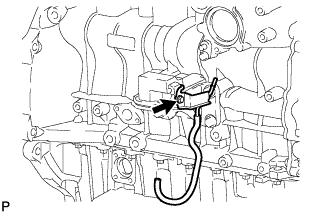
REMOVE NO. 1 VACUUM TRANSMITTING PIPE SUB-ASSEMBLY
-
Remove the bolt, nut and No. 1 vacuum transmitting pipe.
-
-
REMOVE NO. 1 OIL PAN COVER SUB-ASSEMBLY
-
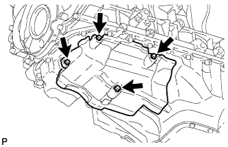
Remove the 4 bolts and No. 1 oil pan cover.
-
-
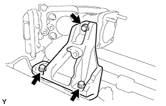
REMOVE FRONT NO. 1 ENGINE MOUNTING BRACKET
-
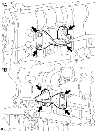
Text in Illustration *A for LH Side *B for RH Side Remove the 8 bolts and 2 front No. 1 engine mounting brackets.
-