ENGINE UNIT (w/ DPF) DISASSEMBLY

Note
-
When replacing the injectors (including shuffling the injectors between the cylinders), common rail or cylinder head, it is necessary to replace the injection pipes with new ones.
-
When replacing the fuel supply pump, common rail, cylinder block, cylinder head, cylinder head gasket or timing gear case, it is necessary to replace the fuel inlet pipe with a new one.
-
REMOVE OIL FILLER CAP SUB-ASSEMBLY
-
REMOVE CYLINDER HEAD COVER SUB-ASSEMBLY
Note
If the cylinder head cover is removed, replace the 4 No. 3 cylinder head cover gaskets with new ones.
-
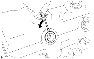
Using a small screwdriver, remove the nozzle holder seal by prying the portion between the nozzle holder seal and the cutout part of the cylinder head cover.
-
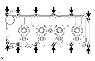
Remove the 10 bolts, 2 nuts, cylinder head cover and cylinder head cover gasket.
-
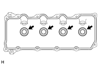
Remove the 4 No. 3 cylinder head cover gaskets from the cylinder head cover.
-
-
REMOVE INJECTOR ASSEMBLY
-
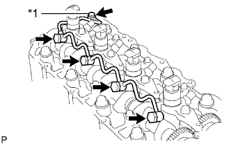
Text in Illustration *1 Union Bolt Remove the union bolt, 4 injector hollow screws, 5 gaskets and nozzle leakage pipe.
Note
-
When removing the nozzle leakage pipe, place a cushion under the pipe.
-
Be careful not to deform or scratch the union seal surface.
-
After removing the nozzle leakage pipe, put it in a plastic bag to prevent foreign matter from contaminating its injector inlet.
-
-
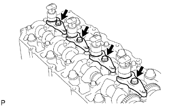
Remove the 4 bolts, 4 washers, 4 No. 1 nozzle holder clamps and 4 injectors.
Tech Tips
Arrange the injectors, No. 1 nozzle holder clamps, washers and bolts in the correct order.
-
Remove the O-ring from each injector.
-
Remove the 4 injection nozzle seats from the cylinder head.
-
-
REMOVE CAMSHAFT TIMING PULLEY
-
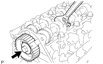
Remove the bolt of the camshaft timing pulley while holding the camshaft with a wrench.
Note
Make sure the timing belt is not installed when removing the bolt of camshaft timing pulley.
-
Remove the camshaft timing pulley.
-
-
REMOVE NO. 2 TIMING BELT COVER
-
Remove the 4 bolts, nut and No. 2 timing belt cover.
-
-
REMOVE CYLINDER BLOCK INSULATOR
-
Remove the cylinder block insulator from the cylinder head.
-
-
REMOVE CAMSHAFT
-
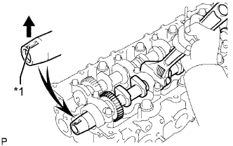
Text in Illustration *1 Key Groove Turn the camshaft with a wrench so that the key groove of the camshaft faces upward.
-
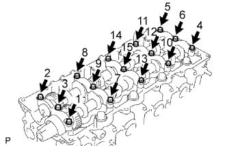
Uniformly loosen the 15 bearing cap bolts in several passes in the sequence shown in the illustration.
-
Remove the 15 bearing cap bolts, 5 bearing caps, oil seal and 2 camshafts.
-
-
REMOVE VALVE LIFTER
-
Remove the valve lifters.
Tech Tips
Arrange the valve lifters in the correct order.
-
-
REMOVE CYLINDER HEAD SUB-ASSEMBLY
-
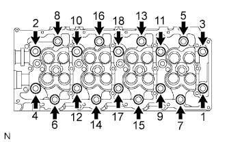
Uniformly loosen the 18 cylinder head bolts in several passes in the sequence shown in the illustration. Then remove the 18 cylinder head bolts and 18 washers.
Note
Head warpage or cracking could result from removing bolts in the incorrect order.
-
Remove the cylinder head from the dowels on the cylinder block and place the cylinder head on wooden blocks on a workbench.
Note
Be careful not to damage the contact surfaces of the cylinder head and cylinder block.
Tech Tips
If the cylinder head is difficult to remove, use a screwdriver to pry between the cylinder head and block.
-
-
REMOVE CYLINDER HEAD GASKET
-
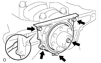
REMOVE WATER PUMP ASSEMBLY
-
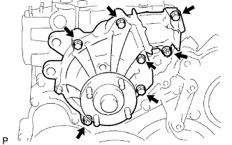
Remove the 5 bolts, 2 nuts, water pump and gasket.
-
-
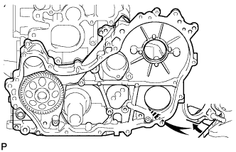
REMOVE TIMING GEAR COVER
Note
As the fuel supply pump is not installed, the injection gear is loose inside the timing gear case. Do not allow the injection gear to fall.
Tech Tips
To prevent the injection gear from falling, temporarily install the fuel supply pump.
-
Remove the 14 bolts and 2 nuts.
-
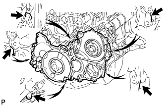
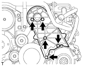
Pry the timing gear cover at the locations shown in the illustration and remove the timing gear cover.
Note
Be careful not to drop the injection gear.
-
Remove the 3 O-rings from the timing gear case.
-
-
REMOVE OIL CHECK VALVE SUB-ASSEMBLY
-
Using a 6 mm hexagon wrench, remove the bolt and oil check valve from the timing gear cover.
-
-
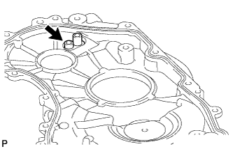
INSPECT OIL CHECK VALVE SUB-ASSEMBLY
-
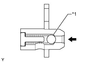
Text in Illustration *1 Ball Push the ball of the oil check valve to check if it is stuck.
If the check valve is stuck, replace the oil check valve sub-assembly.
-
-
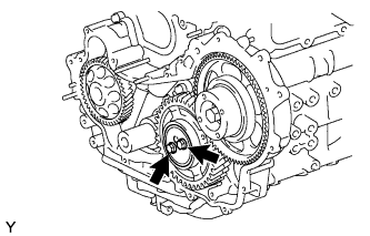
REMOVE INJECTION GEAR
-
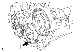
Secure the No. 2 idle sub gear to the No. 1 idle gear with a service bolt.
- Torque:
- 8.0 N*m { 82 kgf*cm, 71 in.*lbf }
Note
If the bolt hole of the No. 2 idle sub gear is not aligned with the bolt hole of the No. 1 idle gear, rotate the crankshaft counterclockwise to align the bolt holes. Then install the service bolt.
-
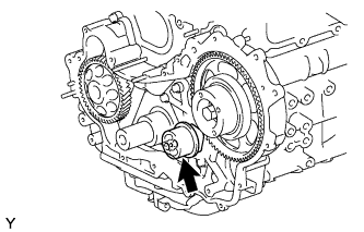
Remove the injection gear.
-
-
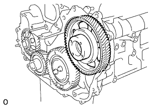
REMOVE NO. 1 CRANKSHAFT POSITION SENSOR PLATE
-
Remove the No. 1 crankshaft position sensor plate.
-
-
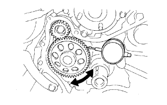
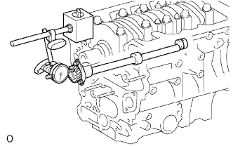
INSPECT BACKLASH OF CRANKSHAFT TIMING GEAR TO OIL PUMP GEAR
-
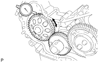
Using a dial indicator, measure the backlash.
Standard gear backlash 0.02 to 0.15 mm (0.000787 to 0.00591 in.) Maximum gear backlash 0.2 mm (0.00787 in.) If the gear backlash is more than the maximum, replace the crankshaft timing gear or timing gear case assembly.
-
-
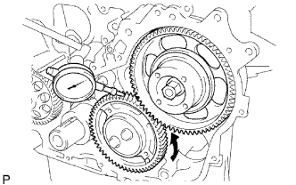
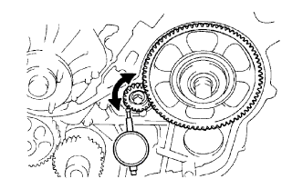
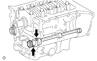
INSPECT BACKLASH OF CRANKSHAFT TIMING GEAR TO NO. 1 IDLE GEAR
-
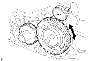
Using a dial indicator, measure the backlash.
Standard gear backlash 0.02 to 0.15 mm (0.000787 to 0.00591 in.) Maximum gear backlash 0.2 mm (0.00787 in.) If the gear backlash is more than the maximum, replace the crankshaft timing gear or No. 1 idle gear.
-
-
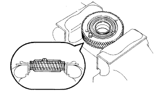
INSPECT NO. 1 IDLE GEAR THRUST CLEARANCE
-
Install the timing gear case, No. 1 idle gear and camshaft timing gear.
-
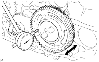
Using a dial indicator, measure the thrust clearance.
Standard thrust clearance 0.06 to 0.11 mm (0.00236 to 0.00433 in.) Maximum thrust clearance 0.3 mm (0.0118 in.) If the thrust clearance is more than the maximum, replace the idle gear thrust plate. If necessary, replace the No. 1 idle gear or No. 1 idle gear shaft.
-
-
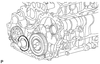
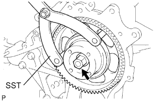
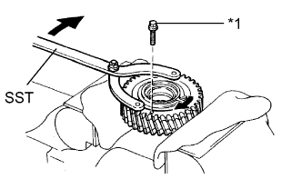
REMOVE CRANKSHAFT TIMING GEAR
-
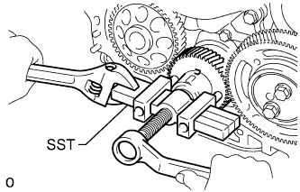
Using SST, remove the crankshaft timing gear.
- SST
- 09950-50013 ( 09951-05010, 09952-05010, 09953-05010, 09954-05021 )
-
-
INSPECT BACKLASH OF INJECTION GEAR TO NO. 1 IDLE GEAR
-
Install the fuel supply pump with the 2 nuts.
- Torque:
- 21 N*m { 214 kgf*cm, 15 ft.*lbf }
-
Using SST, install the injection gear with the nut.
- SST
- 09960-10010 ( 09962-01000, 09963-01000 )
- Torque:
- 64 N*m { 650 kgf*cm, 47 ft.*lbf }
-
Using a dial indicator, measure the backlash.
Standard gear backlash 0.02 to 0.15 mm (0.000787 to 0.00591 in.) Maximum gear backlash 0.2 mm (0.00787 in.) If the gear backlash is more than the maximum, replace the injection gear or No. 1 idle gear.
-
-
REMOVE IDLE GEAR THRUST PLATE
-
Remove the 2 bolts and idle gear thrust plate.
-
-
REMOVE NO. 1 IDLE GEAR
-

Remove the No. 1 idle gear together with the No. 2 idle sub gear.
-
-
REMOVE NO. 1 IDLE GEAR SHAFT
-
Remove the No. 1 idle gear shaft.
-
-
INSPECT BACKLASH OF NO. 1 BALANCESHAFT TO OIL PUMP GEAR
-
Using a dial indicator, measure the backlash.
Standard gear backlash 0.02 to 0.15 mm (0.000787 to 0.00591 in.) Maximum gear backlash 0.2 mm (0.00787 in.) If the gear backlash is more than the maximum, replace the No. 1 balanceshaft sub-assembly or timing gear case assembly.
-
-
INSPECT BACKLASH OF NO. 2 BALANCESHAFT TO INJECTION GEAR
-
Using a dial indicator, measure the backlash.
Standard gear backlash 0.02 to 0.15 mm (0.000787 to 0.00591 in.) Maximum gear backlash 0.2 mm (0.00787 in.) If the gear backlash is more than the maximum, replace the No. 2 balanceshaft assembly or injection gear.
-
Using SST, remove the nut and injection gear.
- SST
- 09960-10010 ( 09962-01000, 09963-01000 )
-
Remove the 2 nuts and fuel supply pump.
-
Remove the gears and timing gear case.
-
-
REMOVE NO. 1 IDLE SUB GEAR
-
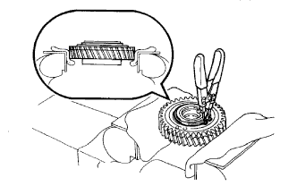
Mount the No. 1 idle gear and No. 2 idle sub gear in a vise.
Note
Be careful not to damage the gears.
-
Text in Illustration *1 Service Bolt Using SST, turn the No. 1 idle sub gear clockwise and remove the service bolt.
- SST
- 09960-10010 ( 09962-01000, 09963-00600 )
-
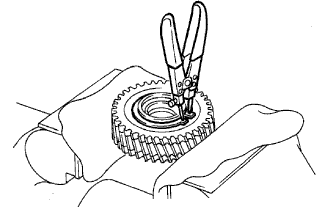
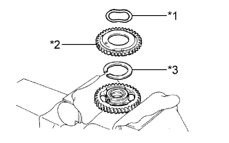
Using snap ring pliers, remove the shaft snap ring.
-
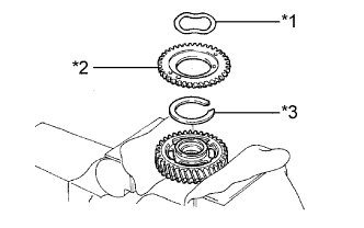
Text in Illustration *1 Wave Washer *2 No. 1 Idle Sub Gear *3 Idle Gear Spring Remove the wave washer, No. 1 idle sub gear and idle gear spring.
-
-
REMOVE NO. 2 IDLE SUB GEAR
-
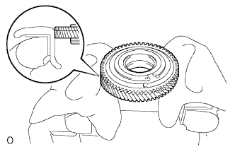
Turn the No. 1 idle gear over and set it in a vise.
Note
Be careful not a damage the gear.
-
Using snap ring pliers, remove the shaft snap ring.
-
Text in Illustration *1 Wave Washer *2 No. 2 Idle Sub Gear *3 Idle Gear Spring Remove the wave washer, No. 2 idle sub gear and idle gear spring.
-
-
REMOVE NO. 2 OIL PAN SUB-ASSEMBLY
-
Remove the 11 bolts and 2 nuts.
-
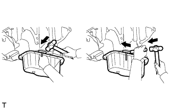
Insert the blade of an oil pan seal cutter between the oil pans. Cut through the applied sealer and remove the No. 2 oil pan.
-
-
REMOVE OIL STRAINER SUB-ASSEMBLY
-
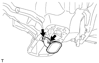
Remove the 2 nuts, oil strainer and gasket.
-
-
REMOVE OIL PAN SUB-ASSEMBLY
-
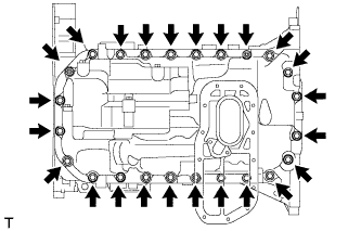
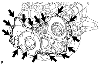
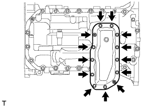
Remove the 22 bolts and 2 nuts.
-
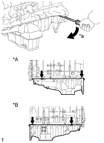
Text in Illustration *A LH Side *B RH Side *a Pry Using a screwdriver, remove the oil pan by prying between the oil pan and cylinder block as shown in the illustration.
Note
Be careful not to damage the contact surfaces of the cylinder block and oil pan.
Tech Tips
Tape the screwdriver tip before use.
-
Remove the gasket.
-
-
REMOVE TIMING GEAR CASE ASSEMBLY
-
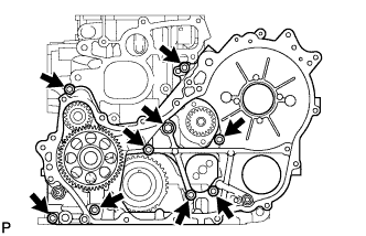
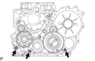
Remove the union bolt and 8 bolts.
-
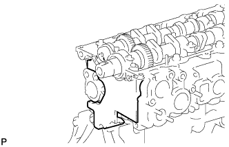
Pry the timing gear case at the location shown in the illustration and remove the gear case and gasket.
-
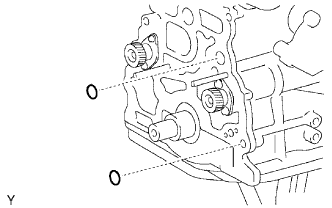
Remove the 2 O-rings.
-
-
INSPECT NO. 1 BALANCESHAFT THRUST CLEARANCE
-
Using a dial indicator, measure the thrust clearance while moving the No. 1 balanceshaft back and forth.
Standard thrust clearance 0.065 to 0.140 mm (0.00256 to 0.00551 in.) Maximum thrust clearance 0.25 mm (0.00984 in.) If the thrust clearance is more than the maximum clearance, replace the balanceshaft thrust washer.
If the thrust clearance is still more than the maximum clearance, replace the No. 1 balanceshaft sub-assembly.
-
-
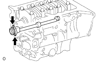
REMOVE NO. 1 BALANCESHAFT SUB-ASSEMBLY
-
Remove the 2 bolts and balanceshaft.
-
-
REMOVE NO. 1 BALANCESHAFT DRIVEN GEAR
-
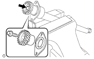
Mount the balanceshaft between aluminum plates in a vise.
Note
Be careful not to damage the balanceshaft.
-
Remove the bolt, balanceshaft driven gear and balanceshaft thrust washer.
-
-
INSPECT NO. 2 BALANCESHAFT THRUST CLEARANCE
-
Using a dial indicator, measure the thrust clearance while moving the No. 2 balanceshaft back and forth.
Standard thrust clearance 0.065 to 0.140 mm (0.00256 to 0.00551 in.) Maximum thrust clearance 0.25 mm (0.00984 in.) If the thrust clearance is more than the maximum clearance, replace the balanceshaft thrust washer.
If the thrust clearance is still more than the maximum clearance, replace the No. 2 balanceshaft sub-assembly.
-
-
REMOVE NO. 2 BALANCESHAFT SUB-ASSEMBLY
-
Remove the 2 bolts and balanceshaft.
-
-
REMOVE NO. 2 BALANCESHAFT DRIVEN GEAR
-
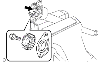
Mount the balanceshaft between aluminum plates in a vise.
Note
Be careful not to damage the balanceshaft.
-
Remove the bolt, balanceshaft driven gear and balanceshaft thrust washer.
-
-
REMOVE REAR ENGINE OIL SEAL RETAINER
-
Remove the 5 bolts.
-
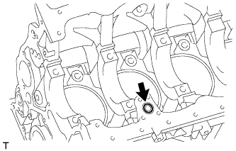
Using a screwdriver, remove the rear engine oil seal retainer by prying between the rear engine oil seal retainer and cylinder block.
-
-
REMOVE FRONT CRANKSHAFT OIL SEAL
-
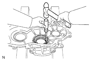
Using a screwdriver and hammer, tap out the oil seal.
-
-
REMOVE SUPPLY PUMP OIL SEAL
-
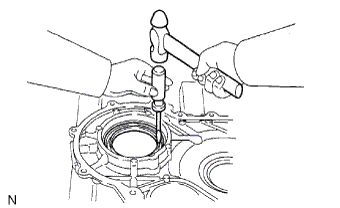
Using a screwdriver and hammer, tap out the oil seal.
-
-
REMOVE REAR CRANKSHAFT OIL SEAL
-
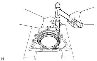
Using a screwdriver and hammer, tap out the oil seal.
-