CYLINDER HEAD GASKET (w/o DPF) INSTALLATION

Note
-
When replacing the injectors (including shuffling the injectors between the cylinders), common rail or cylinder head, it is necessary to replace the injection pipes with new ones.
-
When replacing the fuel supply pump, common rail, cylinder block, cylinder head, cylinder head gasket or timing gear case, it is necessary to replace the fuel inlet pipe with a new one.
-
INSTALL CYLINDER HEAD GASKET
-
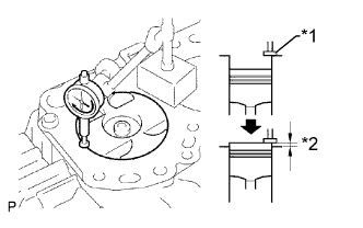
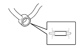
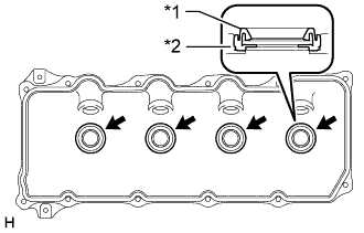
Text in Illustration *1 Measuring Tip *2 Protrusion Find where the piston head protrudes most by slowly turning the crankshaft clockwise and counterclockwise.
-
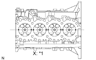
Text in Illustration *1 Measuring Point Measure the piston protrusion of each cylinder at 2 points as shown in the illustration.
-
For the piston protrusion value of each cylinder, use the average of the 2 measurements of each cylinder.
Piston protrusion 0.005 to 0.255 mm (0.000197 to 0.0100 in.) Tech Tips
After installing the piston and connecting rod assembly, if the protrusion is not as specified, remove the piston and connecting rod assembly and reinstall them.
-
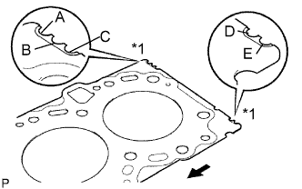
Text in Illustration *1 Cutout Mark 
Front Select a new cylinder head gasket.
Tech Tips
New cylinder head gaskets are available in 5 sizes, and are marked A, B, C, D or E.
New Cylinder Head Gasket Thickness Mark Specified Condition A 0.80 to 0.90 mm (0.0315 to 0.0354 in.) B 0.85 to 0.95 mm (0.0335 to 0.0374 in.) C 0.90 to 1.00 mm (0.0354 to 0.0394 in.) D 0.95 to 1.05 mm (0.0374 to 0.0413 in.) E 1.00 to 1.10 mm (0.0394 to 0.0433 in.)
-
Select the largest piston protrusion value from the measurements made. Then select a new gasket to the table below.
Gasket Size Item Specified Condition Piston protrusion 0.005 to 0.054 mm (0.000197 to 0.00213 in.) 0.055 to 0.104 mm (0.00217 to 0.00409 in.) 0.105 to 0.154 mm (0.00413 to 0.00606 in.) 0.155 to 0.204 mm (0.00610 to 0.00803 in.) 0.205 to 0.255 mm (0.00807 to 0.0100 in.) Use gasket A B C D E
-
-
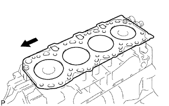
Place the cylinder head gasket on the cylinder block.
Text in Illustration Front Note
Make sure the gasket is installed facing the proper direction.
-
-
INSTALL CYLINDER HEAD SUB-ASSEMBLY
Tech Tips
-
The cylinder head bolts are tightened in 3 progressive steps.
-
If any bolt is broken or deformed, replace it Click here.
-
Place the cylinder head on the cylinder head gasket.
-
Apply a light coat of engine oil on the threads and under the heads of the cylinder head bolts.
-
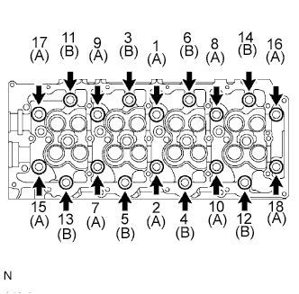
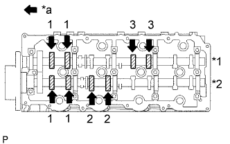
Install the 18 washers with the 18 cylinder head bolts, and uniformly tighten the bolts, in several passes in the sequence shown in the illustration.
- Torque:
- 85 N*m { 867 kgf*cm, 63 ft.*lbf }
Bolt length A 110 mm (4.33 in.) Bolt length B 167 mm (6.57 in.) If any of the cylinder head bolts does not meet the torque specification, replace it.
-
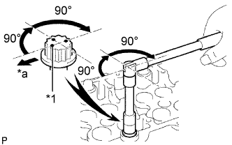
*1 Painted Mark *a Front Mark the front of each cylinder head bolt with paint.
-
Further tighten the cylinder head bolts by 90° in the sequence shown in the illustration above.
-
Tighten the cylinder head bolts by an additional 90°.
-
Check that the painted marks are now facing rearward.
-
-
INSTALL CAMSHAFT
-
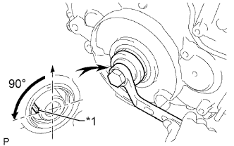
Text in Illustration *1 Key Using the crankshaft pulley bolt, set the No. 1 cylinder to 90° BTDC/compression.
Tech Tips
Set the No. 1 cylinder to 90° BTDC/compression to prevent the top of the piston from hitting against the valve head.
-
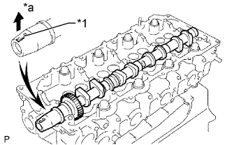
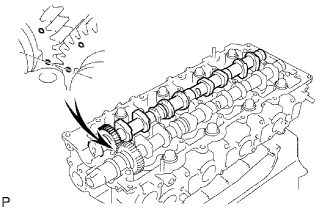
Install the camshaft.
-
Apply MP grease to the thrust portion of the camshaft.
-
Place the camshaft on the cylinder head with the key groove facing upward.
Text in Illustration *1 Key Groove *a Upward -
Align the timing marks (1 dot mark) of the camshaft drive and driven main gears, and set the No. 2 camshaft in place.
-
-
Remove any old seal packing (FIPG material) from the camshaft bearing cap.
-
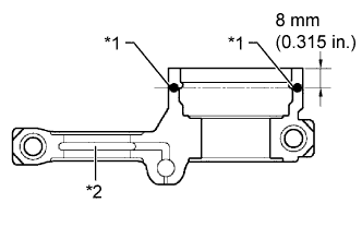
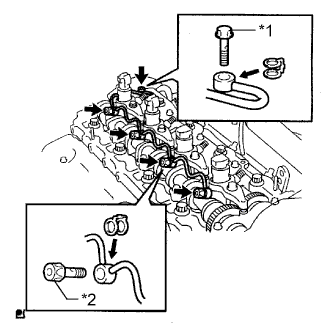
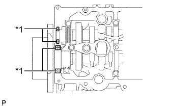
Apply seal packing to the specified areas shown in the illustration.
Text in Illustration *1 Seal Packing *2 Oil Passage Seal packing Toyota Genuine Seal Packing Black, Three Bond 1207B or equivalent Standard seal diameter 4 mm (0.157 in.) Note
-
Do not allow seal packing to contact the oil passage of the bearing cap.
-
After applying seal packing, install the camshaft bearing caps within 3 minutes and tighten the bolts within 15 minutes.
-
Do not start the engine for at least 2 hours after installation.
-
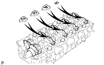
Install the 5 bearing caps to their proper locations.
-
Apply a light coat of engine oil to the threads and under the heads of the bearing cap bolts.
-
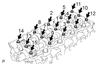
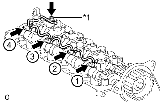
Install and uniformly tighten the 15 bearing cap bolts in several passes in the sequence shown in the illustration.
- Torque:
- 19 N*m { 194 kgf*cm, 14 ft.*lbf }
-
-
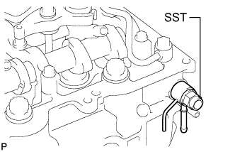
Install a new camshaft oil seal.
-
Apply MP grease to the lip of a new oil seal.
-
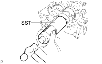
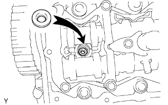
Using SST and a hammer, tap in the oil seal until its surface is flush with the surfaces of the camshaft bearing cap and cylinder head.
- SST
- 09608-06041
-
-
-
INSTALL CYLINDER BLOCK INSULATOR
-
Install the cylinder block insulator to the cylinder head.
-
-
INSTALL NO. 2 TIMING BELT COVER
-
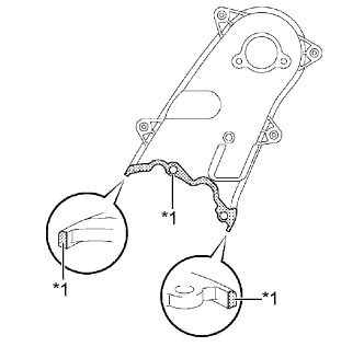
Text in Illustration *1 Seal Packing Apply seal packing (FIPG) to the specified areas shown in the illustration.
Seal packing Toyota Genuine Seal Packing Black, Three Bond 1207B or equivalent Note
After applying seal packing, install the No. 2 timing belt cover within 3 minutes and tighten the bolts and nut within 15 minutes.
-
Install the No. 2 timing belt cover with the 4 bolts and nut.
- Torque:
- 10 N*m { 102 kgf*cm, 7 ft.*lbf }
-
-
INSTALL CAMSHAFT TIMING PULLEY
-
Install the camshaft timing pulley.
-
Install the bolt of the camshaft timing pulley while holding the camshaft with a wrench.
- Torque:
- 98 N*m { 1000 kgf*cm, 72 ft.*lbf }
-
-
INSTALL NO. 1 TIMING BELT IDLER SUB-ASSEMBLY
-
Using a 10 mm hexagon wrench, install a new washer and the No. 1 timing belt idler with the bolt.
- Torque:
- 35 N*m { 357 kgf*cm, 26 ft.*lbf }
-
Check that the idler pulley moves smoothly.
If the idler pulley does not move smoothly, check the installation condition of the idler and washer.
-
-
INSTALL TIMING BELT
-
Install the timing belt Click here.
-
-
INSPECT VALVE CLEARANCE
-
Text in Illustration *1 Exhaust *2 Intake *a Front Check only the valves indicated.
-
Using a feeler gauge, measure the clearance between the valve lifter and camshaft.
Standard Valve Clearance (Cold) Item Specified Condition Intake 0.2 to 0.3 mm (0.00787 to 0.0118 in.) Exhaust 0.35 to 0.45 mm (0.0138 to 0.0177 in.) Write down any valve clearance measurements that are not within the specified range. These measurements will be used later to determine the size of the adjustment lifter to be installed.
-
-
Turn the crankshaft 360° to set the No. 4 cylinder to TDC/compression.
-
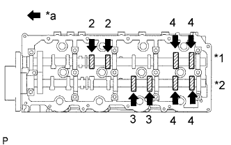
Text in Illustration *1 Exhaust *2 Intake *a Front Check only the valves indicated.
-
Using a feeler gauge, measure the clearance between the valve lifter and camshaft.
Standard Valve Clearance (Cold) Item Specified Condition Intake 0.2 to 0.3 mm (0.00787 to 0.0118 in.) Exhaust 0.35 to 0.45 mm (0.0138 to 0.0177 in.) Write down valve clearance measurements that are not within the specified range. These measurements will be used later to determine the size of the adjustment lifter to be installed.
-
-
-
ADJUST VALVE CLEARANCE
-
w/ DPF:
Remove the camshafts Click here.
-
w/o DPF:
Remove the camshafts Click here.
-
Remove the valve lifters.
-
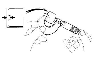
Using a micrometer, measure the thickness of the removed lifter.
-
Calculate the thickness of a new lifter so that the valve clearance is within the specified range.
A B C New lifter thickness Used lifter thickness Measured valve clearance New lifter thickness Intake: A = B + (C - 0.25 mm (0.00984 in.)) Exhaust: A = B + (C - 0.40 mm (0.0157 in.)) -
Select a new lifter with a thickness as close as possible to the calculated values.
Tech Tips
Valve lifters are available in 35 sizes in increments of 0.02 mm (0.000787 in.), from 5.06 mm (0.199 in.) to 5.74 mm (0.226 in.).
-
Install the selected valve lifter.
Text in Illustration *1 Valve Lifter Selection Chart (Intake) *2 Installed lifter thickness mm (in.) *3 Measured clearance mm (in.) - - 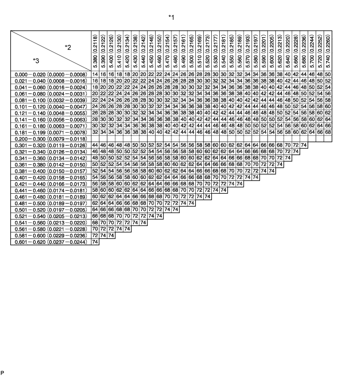
Text in Illustration *1 Valve Lifter Selection Chart (Intake) *2 Installed lifter thickness mm (in.) *3 Measured clearance mm (in.) - - Standard intake valve clearance (Cold) 0.2 to 0.3 mm (0.00787 to 0.0118 in.) EXAMPLE A 5.25 mm (0.207 in.) lifter is installed, and the measured clearance is 0.4 mm (0.0157 in.). Replace the 5.25 mm (0.207 in.) lifter with a No. 40 lifter. New Lifter Thickness Lifter No. Specified Condition Lifter No. Specified Condition Lifter No. Specified Condition 06 5.06 mm (0.1992 in.) 30 5.30 mm (0.2087 in.) 54 5.54 mm (0.2181 in.) 08 5.08 mm (0.2000 in.) 32 5.32 mm (0.2094 in.) 56 5.56 mm (0.2189 in.) 10 5.10 mm (0.2008 in.) 34 5.34 mm (0.2102 in.) 58 5.58 mm (0.2197 in.) 12 5.12 mm (0.2016 in.) 36 5.36 mm (0.2110 in.) 60 5.60 mm (0.2205 in.) 14 5.14 mm (0.2024 in.) 38 5.38 mm (0.2118 in.) 62 5.62 mm (0.2213 in.) 16 5.16 mm (0.2031 in.) 40 5.40 mm (0.2126 in.) 64 5.64 mm (0.2220 in.) 18 5.18 mm (0.2039 in.) 42 5.42 mm (0.2134 in.) 66 5.66 mm (0.2228 in.) 20 5.20 mm (0.2047 in.) 44 5.44 mm (0.2142 in.) 68 5.68 mm (0.2236 in.) 22 5.22 mm (0.2055 in.) 46 5.46 mm (0.2150 in.) 70 5.70 mm (0.2244 in.) 24 5.24 mm (0.2063 in.) 48 5.48 mm (0.2157 in.) 72 5.72 mm (0.2252 in.) 26 5.26 mm (0.2071 in.) 50 5.50 mm (0.2165 in.) 74 5.74 mm (0.2260 in.) 28 5.28 mm (0.2079 in.) 52 5.52 mm (0.2173 in.) - - 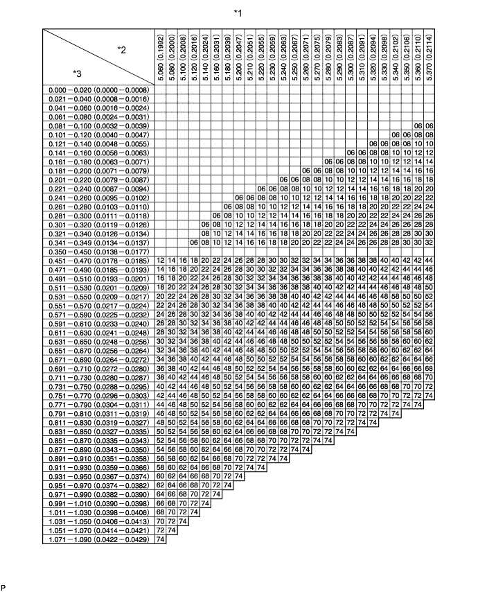
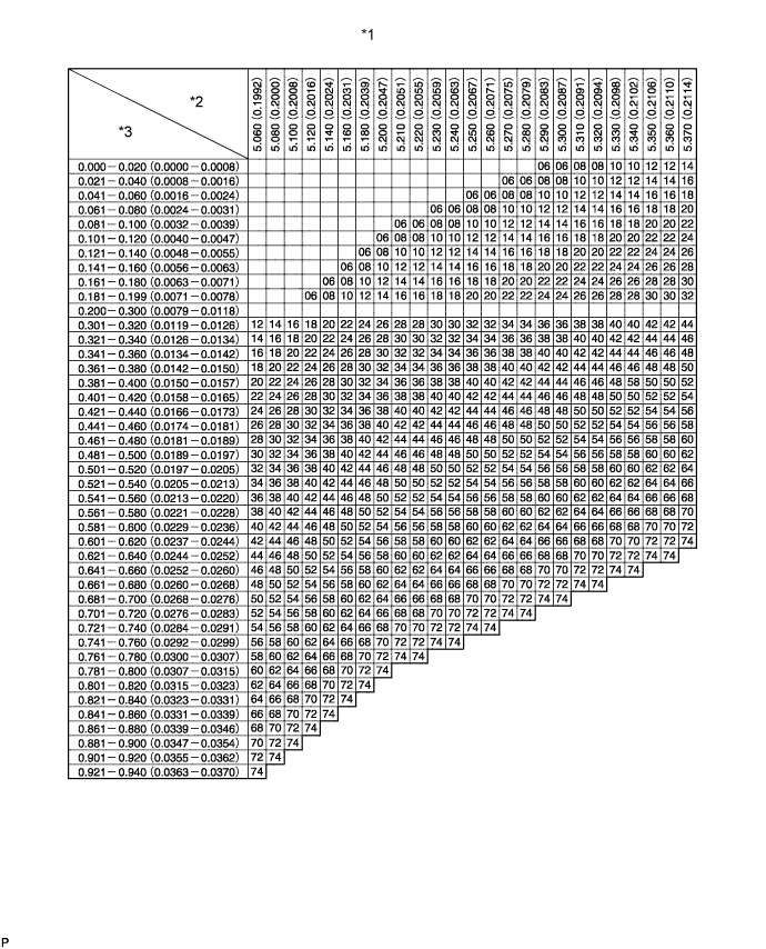
Text in Illustration *1 Valve Lifter Selection Chart (Exhaust) *2 Installed lifter thickness mm (in.) *3 Measured clearance mm (in.) - - 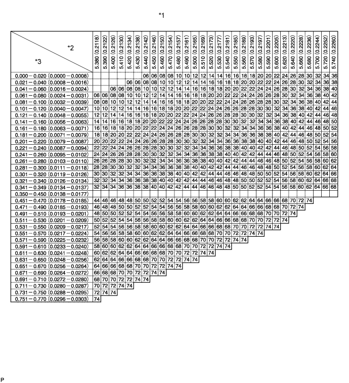
Text in Illustration *1 Valve Lifter Selection Chart (Exhaust) *2 Installed lifter thickness mm (in.) *3 Measured clearance mm (in.) - - Standard exhaust valve clearance (Cold) 0.35 to 0.45 mm (0.0138 to 0.0177 in.) EXAMPLE A 5.34 mm (0.210 in.) lifter is installed, and the measured clearance is 0.48 mm (0.0189 in.). Replace the 5.34 mm (0.210 in.) lifter with a No. 42 lifter. New Lifter Thickness Lifter No. Specified Condition Lifter No. Specified Condition Lifter No. Specified Condition 06 5.06 mm (0.1992 in.) 30 5.30 mm (0.2087 in.) 54 5.54 mm (0.2181 in.) 08 5.08 mm (0.2000 in.) 32 5.32 mm (0.2094 in.) 56 5.56 mm (0.2189 in.) 10 5.10 mm (0.2008 in.) 34 5.34 mm (0.2102 in.) 58 5.58 mm (0.2197 in.) 12 5.12 mm (0.2016 in.) 36 5.36 mm (0.2110 in.) 60 5.60 mm (0.2205 in.) 14 5.14 mm (0.2024 in.) 38 5.38 mm (0.2118 in.) 62 5.62 mm (0.2213 in.) 16 5.16 mm (0.2031 in.) 40 5.40 mm (0.2126 in.) 64 5.64 mm (0.2220 in.) 18 5.18 mm (0.2039 in.) 42 5.42 mm (0.2134 in.) 66 5.66 mm (0.2228 in.) 20 5.20 mm (0.2047 in.) 44 5.44 mm (0.2142 in.) 68 5.68 mm (0.2236 in.) 22 5.22 mm (0.2055 in.) 46 5.46 mm (0.2150 in.) 70 5.70 mm (0.2244 in.) 24 5.24 mm (0.2063 in.) 48 5.48 mm (0.2157 in.) 72 5.72 mm (0.2252 in.) 26 5.26 mm (0.2071 in.) 50 5.50 mm (0.2165 in.) 74 5.74 mm (0.2260 in.) 28 5.28 mm (0.2079 in.) 52 5.52 mm (0.2173 in.) - - -
w/ DPF:
Install the camshafts Click here.
-
w/o DPF:
Install the camshafts Click here.
-
-
INSTALL INJECTOR ASSEMBLY
Note
Be sure to install the injector, No. 1 nozzle holder clamp, washer and bolt in their original positions.
-
Install 4 new injection nozzle seats to the cylinder head.
-
Apply a small amount of clean engine oil to 4 new O-rings.
-
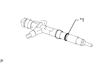
Text in Illustration *1 New O-Ring Install an O-ring to each injector as shown in the illustration.
-
Insert the 4 injectors into the cylinder head.
Note
-
Insert the injector until it touches the injection nozzle seat surface.
-
After installing the injector to the cylinder head, the O-ring may prevent the injector from fully seating. If so, pull out the injector and reinstall it.
-
Always return an injector to the same place it was removed from.
-
-
For an injector that has been replaced with a new injector, register the injector compensation code Click here.
-
Text in Illustration *1 Washer *a Downward Temporarily install 4 new washers and the 4 No. 1 nozzle holder clamps with the 4 bolts.
Tech Tips
Apply a small amount of engine oil to the threads and under the heads of the clamp bolts.
-
Temporarily install the 4 injection pipes with the union nuts.
Tech Tips
To position the injectors, loosely tighten the union nut.
-
Check the nozzle leakage pipe. Check that there are no scratches or dents on the 5 union seal surfaces.
If scratches or dents are present, replace the nozzle leakage pipe.
-
Text in Illustration *1 Union Bolt *2 Hollow Screw Set the leakage pipe and 5 new gaskets in place.
-
Apply a small amount of oil to the 4 injector hollow screws and union bolt.
-
Temporarily install the leakage pipe with the 4 injector hollow screws and union bolt.
-
Tighten the 4 holder clamp bolts.
- Torque:
- 22 N*m { 220 kgf*cm, 16 ft.*lbf }
-
Text in Illustration *1 Union Bolt Tighten the 4 hollow screws in order from 1 to 4.
- Torque:
- 16 N*m { 163 kgf*cm, 12 ft.*lbf }
Note
If a hollow screw is accidentally tightened beyond the torque specification, it must be replaced.
-
Tighten the union bolt.
- Torque:
- 13 N*m { 127 kgf*cm, 9 ft.*lbf }
Note
If the union bolt is accidentally tightened beyond the torque specification, it must be replaced.
-
Remove the 4 injection pipes.
-
-
INSPECT FOR FUEL LEAK
-
Check that there are no leaks from the nozzle leakage pipe connection.
-
Install the gasket and No. 2 nozzle leakage pipe to the cylinder head with SST (check valve).
Part No. 23762-27010 (No. 2 nozzle leakage pipe) - SST
- 09280-00010
- Torque:
- 21 N*m { 214 kgf*cm, 15 ft.*lbf }
-
Apply a small amount of soapy water (or other fluid for detecting fuel leakage) on the nozzle leakage pipe connection.
-
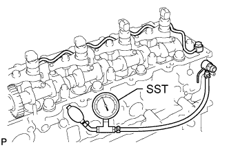
Install SST (turbocharger pressure gauge) to the fuel return side of the leakage pipe, maintain 100 kPa (1.0 kgf/cm2, 15 psi) of pressure for 60 seconds and check that no bubbles form.
- SST
- 09992-00242
-
After checking for fuel leaks, wipe off the soapy water from the leakage pipe connection.
-
Remove SST, the No. 2 nozzle leakage pipe and gasket.
Note
Never reinstall the disassembled union bolt to the engine.
-
-
-
INSTALL CYLINDER HEAD COVER SUB-ASSEMBLY
-
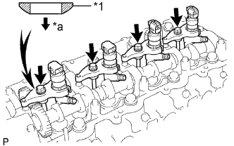
Text in Illustration *1 No. 3 Cylinder Head Cover Gasket *2 Cylinder Head Cover Install 4 new No. 3 cylinder head cover gaskets to the cylinder head cover in the directions shown in the illustration.
Note
-
Do not install the No. 3 cylinder head cover gaskets at an angle.
-
Check that there is no foreign matter at the installation location of the No. 3 cylinder head cover gaskets.
-
-
Remove any old seal packing (FIPG material) from the cylinder head.
-
Text in Illustration *1 Seal Packing Apply seal packing to the areas shown in the illustration.
Seal packing Toyota Genuine Seal Packing Black, Three Bond 1207B or equivalent Note
-
Remove any oil from the contact surface.
-
Install the cylinder head cover within 3 minutes after applying seal packing.
-
Do not start the engine for at least 2 hours after installation.
-
-
Install a new gasket and the cylinder head cover with the 10 bolts and 2 nuts.
- Torque:
- 9.0 N*m { 92 kgf*cm, 80 in.*lbf }
-
-
INSTALL NOZZLE HOLDER SEAL
-
Install 4 new nozzle holder seals.
-
-
INSTALL NO. 3 VACUUM TRANSMITTING PIPE SUB-ASSEMBLY
-
Install the No. 3 vacuum transmitting pipe with the bolt.
- Torque:
- 18 N*m { 184 kgf*cm, 13 ft.*lbf }
-
Connect the vacuum hose.
-
-
INSTALL NO. 2 CYLINDER HEAD COVER SUB-ASSEMBLY
-
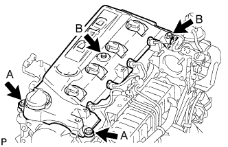
Install the No. 2 cylinder head cover with the 4 bolts.
- Torque:
- for bolt A
- 18 N*m { 184 kgf*cm, 13 ft.*lbf }
- for bolt B
- 8.0 N*m { 82 kgf*cm, 71 in.*lbf }
-
-
INSTALL COMMON RAIL ASSEMBLY
-
Install the common rail and No. 2 intake manifold insulator with the 2 bolts.
- Torque:
- 38 N*m { 387 kgf*cm, 28 ft.*lbf }
-
Connect the fuel pressure sensor connectors and pressure discharge valve connector.
-
-
INSTALL NO. 2 INTAKE MANIFOLD INSULATOR
-
Install the No. 2 intake manifold insulator.
-
-
INSTALL FUEL INLET PIPE SUB-ASSEMBLY
-
Temporarily install the fuel inlet pipe with the union nuts.
Note
-
When replacing the fuel supply pump, it is necessary to replace the fuel inlet pipe with a new one.
-
Keep the fuel inlet pipe free of foreign matter.
-
-
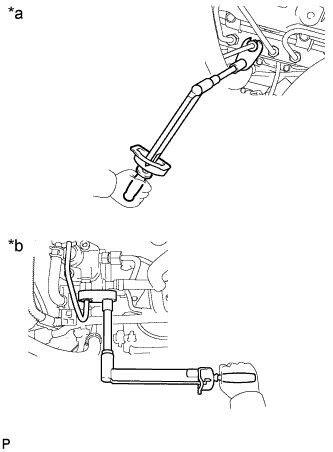
Text in Illustration *a Common Rail Side *b Fuel Supply Pump Side Using a 17 mm union nut wrench, tighten the fuel inlet pipe union nut on the common rail side.
- Torque:
- 35 N*m { 357 kgf*cm, 26 ft.*lbf }
Note
Use the formula to calculate special torque values for situations where a union nut wrench is combined with a torque wrench Click here.
-
Using a 17 mm union nut wrench, tighten the fuel inlet pipe union nut on the fuel supply pump side.
- Torque:
- 35 N*m { 357 kgf*cm, 26 ft.*lbf }
Note
Use the formula to calculate special torque values for situations where a union nut wrench is combined with a torque wrench Click here.
-
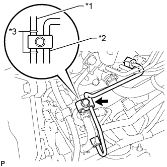
Text in Illustration *1 No. 2 Nozzle Leakage Pipe *2 Fuel Inlet Pipe *3 Spool Install the clamp with the bolt.
- Torque:
- 5.0 N*m { 51 kgf*cm, 44 in.*lbf }
Note
-
Install the clamp between the spools.
-
Do not overlap the clamp and spool.
-
-
INSTALL GLOW PLUG ASSEMBLY
-
Install the glow plugs Click here.
-
-
INSTALL INTAKE MANIFOLD
-
Install the intake manifold Click here.
-
-
INSTALL EXHAUST MANIFOLD WITH TURBOCHARGER
-
Install the exhaust manifold with turbocharger Click here.
-
-
ADD ENGINE OIL
-
Add new engine oil.
Standard Oil Grade Item Oil Grade Oil Viscosity (SAE) w/ DPF ACEA C2
(Using engine oil other than ACEA C2 may damage catalytic converter)
- 0W-30
- 5W-30
(0W-30 is best choice for fuel economy and good starting in cold weather)
w/o DPF G-DLD1, API CF-4, CF or ACEA B1
(You may also use API CE or CD)
- 5W-30
- 10W-30
- 15W-40
- 20W-50
Standard Capacity Item Specified Condition Drain and refill without oil filter change 6.7 liters (7.1 US qts, 5.9 Imp. qts) Drain and refill with oil filter change 7.0 liters (7.4 US qts, 6.2 Imp. qts) Dry fill 7.5 liters (7.9 US qts, 6.6 Imp. qts) -
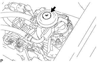
Install the oil filler cap.
-
-
CONNECT CABLE TO NEGATIVE BATTERY TERMINAL
Note
When disconnecting the cable, some systems need to be initialized after the cable is reconnected Click here.
-
BLEED AIR FROM FUEL SYSTEM
-
Using the hand pump mounted on the fuel filter cap, bleed the air from the fuel system. Continue pumping until the pump resistance increases.
Note
-
The maximum hand pump pumping speed is 2 strokes per second.
-
The hand pump must be pushed with a full stroke during pumping.
-
When the fuel pressure at the supply pump inlet port reaches a saturated pressure, the hand pump resistance increases.
-
If pumping is interrupted during the air bleeding process, fuel in the fuel line may return to the fuel tank. Continue pumping until the hand pump resistance increases.
-
If the hand pump resistance does not increase despite consecutively pumping 200 times or more, there may be a fuel leak between the fuel tank and fuel filter, the hand pump may be malfunctioning, or the vehicle may have run out of fuel.
-
If air bleeding using the hand pump is incomplete, the common rail pressure does not rise to the pressure range necessary for normal use and the engine cannot be started.
-
-
Start the engine.
Note
-
Even if air bleeding using the hand pump has been completed, the starter may need to be cranked for 10 seconds or more to start the engine.
-
Do not crank the engine continuously for more than 20 seconds. The battery may be discharged.
-
Use a fully-charged battery.
-
When the engine can be started, proceed to the next step.
-
If the engine cannot be started, bleed the air again using the hand pump until the hand pump resistance increases (refer to the procedures above). Then start the engine.
-
-
Turn the ignition switch off.
-
Connect the intelligent tester to the DLC3.
-
Turn the ignition switch on (IG) and turn the intelligent tester on.
-
Clear the DTCs Click here.
-
Start the engine.*1
-
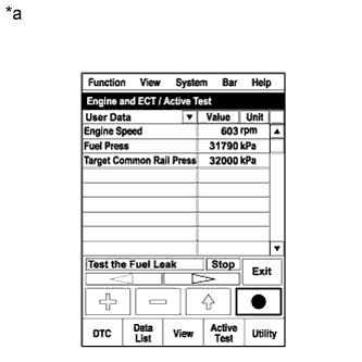
Text in Illustration *a Reference
Active Test Operation
Enter the following menus: Powertrain / Engine and ECT / Active Test / Test the Fuel Leak.*2
-
Perform the following test 5 times with on/off intervals of 10 seconds: Active Test / Test the Fuel Leak.*3
-
Allow the engine to idle for 3 minutes or more after performing the Active Test for the 5th time.
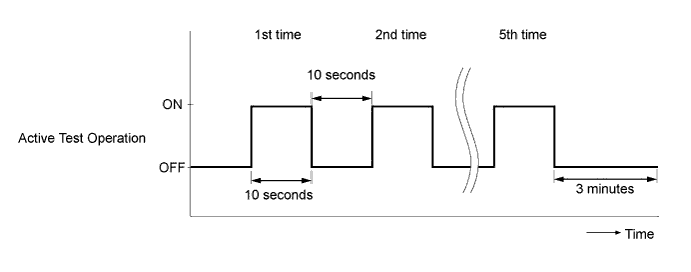
Tech Tips
When the Active Test "Test the Fuel Leak" is used to change the pump control mode, the actual fuel pressure inside the common rail drops below the target fuel pressure when the Active Test is off, but this is normal and does not indicate a pump malfunction.
-
Enter the following menus: Powertrain / Engine and ECT / DTC.
-
Read Current DTCs.
-
Clear the DTCs Click here.
Tech Tips
It is necessary to clear the DTCs as DTC P1604 or P1605 may be stored when air is bled from the fuel system after replacing or repairing fuel system parts.
-
Repeat steps *1 to *3.
-
Enter the following menus: Powertrain / Engine and ECT / DTC.
-
Read Current DTCs.
OK No DTCs are output.
-
-
ADD ENGINE COOLANT
-
Tighten the radiator drain cock plug by hand.
-
Tighten the cylinder block drain cock plug.
- Torque:
- 8.0 N*m { 82 kgf*cm, 71 in.*lbf }
-
Fill the radiator with TOYOTA Super Long Life Coolant (SLLC) to the B line of the reservoir tank.
Standard Capacity Item Specified Condition for Automatic Transmission w/ Rear Heater 14.9 liters (15.7 US qts, 13.1 Imp. qts) w/o Rear Heater 13.1 liters (13.8 US qts, 11.5 Imp. qts) for Manual Transmission w/ Rear Heater 15.0 liters (15.8 US qts, 13.2 Imp. qts) w/o Rear Heater 13.2 liters (13.9 US qts, 11.6 Imp. qts) Tech Tips
-
TOYOTA vehicles are filled with TOYOTA SLLC at the factory. In order to avoid damage to the engine cooling system and other technical problems, only use TOYOTA SLLC or similar high quality ethylene glycol based non-silicate, non-amine, non-nitrite, non-borate coolant with long-life hybrid organic acid technology (coolant with long-life hybrid organic acid technology consists of a combination of low phosphates and organic acids).
-
Please contact your TOYOTA dealer for further details.
-
for Cold Area Specification Vehicles:
Please contact any authorized TOYOTA dealer or repairer or another duly qualified and equipped professional for further details.
Note
Never use water as a substitute for engine coolant.
-
-
Press the inlet and outlet radiator hoses several times by hand, and then check the level of the coolant.
If the coolant level drops below the B line, add TOYOTA SLLC to the B line.
-
Install the radiator reservoir cap.
-
Using a wrench, install the vent plug.
- Torque:
- 2.0 N*m { 20 kgf*cm, 18 in.*lbf }
-
Bleed air from the cooling system.
-
Warm up the engine until the thermostat opens. While the thermostat is open, circulate the coolant for several minutes.
-
Maintain the engine speed at 2500 to 3000 rpm.
-
Press the inlet and outlet radiator hoses several times by hand to bleed air.
CAUTION:
When pressing the radiator hoses:
-
Wear protective gloves.
-
Be careful as the radiator hoses are hot.
-
Keep your hands away from the radiator fan.
-
-
Stop the engine and wait until the coolant cools down to ambient temperature.
CAUTION:
Do not remove the radiator reservoir cap while the engine and radiator are still hot. Pressurized, hot engine coolant and steam may be released and cause serious burns.
-
-
After the coolant cools down, check that the coolant level is at the FULL line.
If the coolant level is below the FULL line, add TOYOTA SLLC to the FULL line.
-
-
INSPECT FOR COOLANT LEAK
Note
Before each inspection, turn the A/C switch off.
CAUTION:
Do not remove the radiator reservoir cap while the engine and radiator are still hot. Pressurized, hot engine coolant and steam may be released and cause serious burns.
-
Fill the radiator with coolant and attach a radiator cap tester.
-
Warm up the engine.
-
Using the radiator cap tester, increase the pressure inside the radiator to 123 kPa (1.3 kgf/cm2, 18 psi), and check that the pressure does not drop.
If the pressure drops, check the hoses, radiator and water pump for leaks. If no external leaks are found, check the heater core, cylinder block and head.
-
-
INSPECT FOR OIL LEAK
-
Start the engine. Make sure that there are no oil leaks from the areas that were worked on.
-
-
INSPECT FOR FUEL LEAK
CAUTION:
-
During Active Test mode, engine speed becomes high and combustion noise becomes loud, so pay attention.
-
During Active Test mode, fuel becomes highly pressurized. Be extremely careful not to expose your eyes, hands, or body to escaped fuel.
-
Check that there are no leaks from any part of the fuel system when the engine is stopped. If there is fuel leakage, repair or replace parts as necessary.
-
Start the engine and check that there are no leaks from any part of the fuel system. If there is fuel leakage, repair or replace parts as necessary.
-
Disconnect the return hose from the common rail.
-
Start the engine and check for fuel leaks from the return pipe.
If there is fuel leakage, replace the common rail.
-
Connect the intelligent tester to the DLC3.
-
Start the engine and turn the intelligent tester on.
-
Select the Fuel Leak test from the Active Test mode on the intelligent tester.
-
If the intelligent tester is not available, fully depress the accelerator pedal quickly. Increase the engine speed to the maximum and maintain that speed for 2 seconds. Repeat this operation several times.
-
Check that there are no leaks from any part of the fuel system.
Note
A return pipe leakage of less than 10 cc (0.6 cu in.) per minute is acceptable.
If there is fuel leakage, repair or replace parts as necessary.
-
Reconnect the return hose to the common rail.
-
-
INSPECT ENGINE OIL LEVEL
-
Warm up the engine, stop the engine and wait 5 minutes. The engine oil level should be between the dipstick low level mark and full level mark.
If low, check for leakage and add oil up to the full level mark.
Note
Do not fill engine oil above the full level mark.
-
-
INSTALL NO. 1 ENGINE UNDER COVER SUB-ASSEMBLY
-
Install the No. 1 engine under cover with the 4 bolts.
- Torque:
- 29 N*m { 296 kgf*cm, 21 ft.*lbf }
-
-
INSTALL FRONT BUMPER LOWER COVER
-
Install the lower front bumper cover with the clip and 5 bolts.
- Torque:
- 8.0 N*m { 82 kgf*cm, 71 in.*lbf }
-