CYLINDER HEAD GASKET (w/o DPF) REMOVAL

Note
-
When replacing the injectors (including shuffling the injectors between the cylinders), common rail or cylinder head, it is necessary to replace the injection pipes with new ones.
-
When replacing the fuel supply pump, common rail, cylinder block, cylinder head, cylinder head gasket or timing gear case, it is necessary to replace the fuel inlet pipe with a new one.
-
DISCONNECT CABLE FROM NEGATIVE BATTERY TERMINAL
Note
-
After turning the ignition switch off, waiting time may be required before disconnecting the cable from the battery terminal. Therefore, make sure to read the disconnecting the cable from the battery terminal notice before proceeding with work Click here.
-
When disconnecting the cable, some systems need to be initialized after the cable is reconnected Click here.
-
-
REMOVE FRONT BUMPER LOWER COVER
-
Remove the clip, 5 bolts and front bumper lower cover.
-
-
REMOVE NO. 1 ENGINE UNDER COVER SUB-ASSEMBLY
-
Remove the 4 bolts and No. 1 engine under cover.
-
-
DRAIN ENGINE COOLANT
CAUTION:
Do not remove the radiator cap while the engine and radiator are still hot. Pressurized, hot engine coolant and steam may be released and cause serious burns.
-
Loosen the radiator drain cock plug.
Tech Tips
Collect the coolant in a container and dispose of it according to the regulations in your area.
-
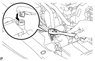
Drain the coolant by removing the reservoir cap and, using a wrench, remove the vent plug.
-
Loosen the cylinder block drain cock plug.
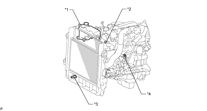
Text in Illustration *1 Radiator Reservoir *2 Vent Plug *3 Radiator Drain Cock Plug *4 Cylinder Block Drain Cock Plug
-
-
DRAIN ENGINE OIL
-
Remove the oil filler cap.
-
Remove the oil pan drain plug and gasket, and then drain the engine oil into a container.
-
Wipe the oil pan and drain plug.
-
Install a new gasket and the oil pan drain plug.
- Torque:
- 34 N*m { 347 kgf*cm, 25 ft.*lbf }
-
-
REMOVE EXHAUST MANIFOLD WITH TURBOCHARGER
-
Remove the exhaust manifold with turbocharger Click here.
-
-
REMOVE INTAKE MANIFOLD
-
Remove the intake manifold Click here.
-
-
REMOVE GLOW PLUG ASSEMBLY
-
Remove the glow plugs Click here.
-
-
REMOVE NO. 2 INTAKE MANIFOLD INSULATOR
-
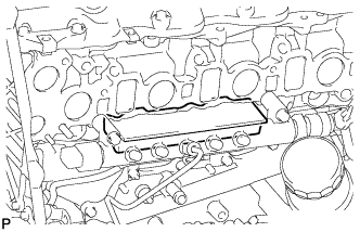
Remove the No. 2 intake manifold insulator.
-
-
REMOVE FUEL INLET PIPE SUB-ASSEMBLY
-
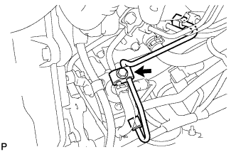
Remove the bolt and clamp.
-
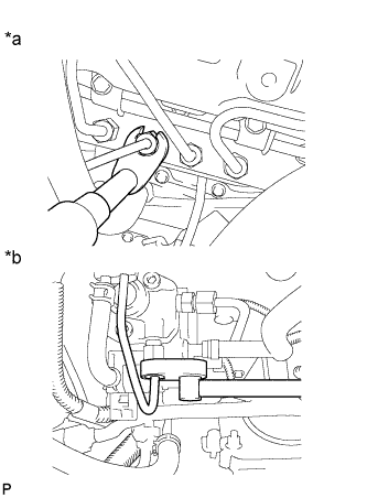
Text in Illustration *a Common Rail Side *b Fuel Supply Pump Side Using a 17 mm union nut wrench, loosen the union nuts and remove the fuel inlet pipe.
-
-
REMOVE COMMON RAIL ASSEMBLY
-
Disconnect the fuel pressure sensor connector and pressure discharge valve connector.
-
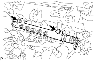
Remove the 2 bolts, common rail and No. 2 intake manifold insulator.
Note
Do not remove the pressure discharge valve and fuel pressure sensor.
-
-
REMOVE NO. 2 CYLINDER HEAD COVER SUB-ASSEMBLY
-
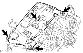
Remove the 4 bolts and No. 2 cylinder head cover.
-
-
REMOVE NO. 3 VACUUM TRANSMITTING PIPE SUB-ASSEMBLY
-
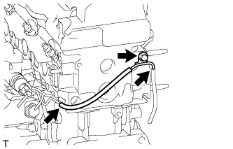
Disconnect the vacuum hose.
-
Remove the bolt and No. 3 vacuum transmitting pipe.
-
-
REMOVE NOZZLE HOLDER SEAL
-
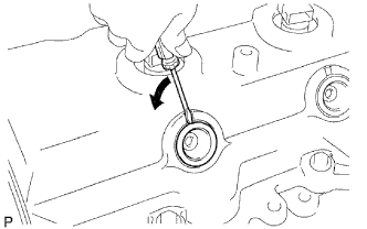
Using a small screwdriver, remove the 4 holder seals by prying between each holder seal and the cutout part of the cylinder head cover.
-
-
REMOVE CYLINDER HEAD COVER SUB-ASSEMBLY
Note
If the cylinder head cover is removed, replace the 4 No. 3 cylinder head cover gaskets with new ones.
-
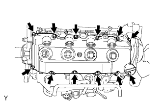
Remove the 10 bolts, 2 nuts, cylinder head cover and gasket.
-
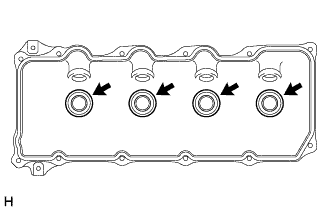
Remove the 4 No. 3 cylinder head cover gaskets from the cylinder head cover.
-
-
REMOVE INJECTOR ASSEMBLY
-
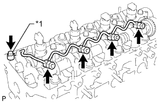
Text in Illustration *1 Union Bolt Remove the union bolt, 4 injector hollow screws, 5 gaskets and nozzle leakage pipe.
Note
-
When removing the nozzle leakage pipe, place a cushion under the pipe.
-
Be careful not to deform or scratch the union seal surface.
-
After removing the nozzle leakage pipe, put it in a plastic bag to prevent foreign matter from contaminating its injector inlet.
-
-
Remove the 4 bolts, 4 washers, 4 No. 1 nozzle holder clamps and 4 injectors.
Tech Tips
Arrange the injectors, No. 1 nozzle holder clamps, washers and bolts in the correct order.
-
Remove the O-ring from each injector.
-
Remove the 4 injection nozzle seats from the cylinder head.
-
-
REMOVE TIMING BELT
-
Remove the timing belt Click here.
-
-
REMOVE NO. 1 TIMING BELT IDLER SUB-ASSEMBLY
Note
When inspecting the No. 1 timing belt idler, do not remove it unless absolutely necessary.
-
Using a 10 mm hexagon wrench, remove the bolt, No. 1 timing belt idler and washer.
-
-
REMOVE CAMSHAFT TIMING PULLEY
-
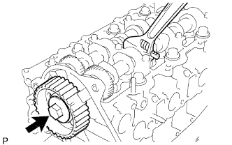
Remove the bolt of the camshaft timing pulley while holding the camshaft with a wrench.
Note
Make sure the timing belt is not installed when removing the bolt of camshaft timing pulley.
-
Remove the camshaft timing pulley.
-
-
REMOVE NO. 2 TIMING BELT COVER
-
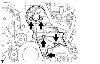
Remove the 4 bolts, nuts and No. 2 timing belt cover.
-
-
REMOVE CYLINDER BLOCK INSULATOR
-
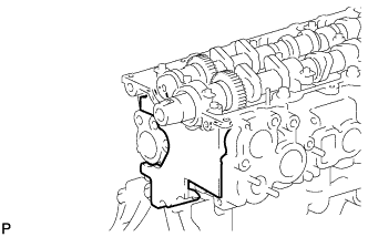
Remove the cylinder block insulator from the cylinder head.
-
-
REMOVE CAMSHAFT
-
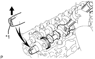
Text in Illustration *1 Key Groove Turn the camshaft with a wrench so that the key groove of the camshaft faces upward.
-
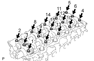
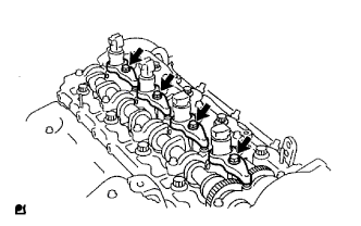
Uniformly loosen the 15 bearing cap bolts in several passes in the sequence shown in the illustration.
-
Remove the 15 bearing cap bolts, 5 bearing caps, oil seal and 2 camshafts.
-
-
REMOVE CYLINDER HEAD SUB-ASSEMBLY
-
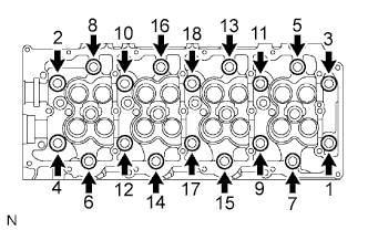
Uniformly loosen the 18 cylinder head bolts in several passes in the sequence shown in the illustration. Then remove the 18 cylinder head bolts and 18 washers.
Note
Head warpage or cracking could result from removing bolts in the incorrect order.
-
Remove the cylinder head from the dowels on the cylinder block and place the cylinder head on wooden blocks on a workbench.
Tech Tips
If the cylinder head is difficult to remove, use a screwdriver to pry between the cylinder head and block.
Note
Be careful not to damage the contact surfaces of the cylinder head and cylinder block.
-
-
REMOVE CYLINDER HEAD GASKET