CYLINDER HEAD REPLACEMENT

-
REPLACE INTAKE VALVE GUIDE BUSH
-
Heat the cylinder head to 80 to 100°C (176 to 212°F).
-
Place the cylinder head on wooden blocks.
-
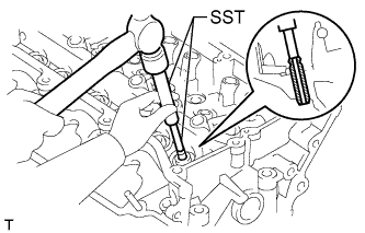
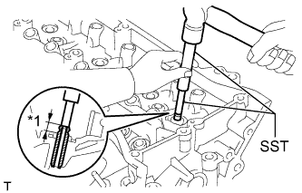
Using SST and a hammer, tap out the intake valve guide bushes.
- SST
- 09201-10000 ( 09201-01050 )
- 09950-70010 ( 09951-07100 )
-
Using a caliper gauge, measure the intake valve guide bush bore diameter of the cylinder head.
Standard Bush Bore Diameter Item Specified Condition STD 10.285 to 10.306 mm (0.4049 to 0.4057 in.) O/S 0.05 10.335 to 10.356 mm (0.4069 to 0.4077 in.) -
Select a new valve guide bush.
New Guide Bush Item Specified Condition Bush Bore Diameter 10.285 to 10.306 mm (0.4049 to 0.4057 in.) 10.335 to 10.356 mm (0.4069 to 0.4077 in.) Use Bush STD O/S 0.05 If the bush bore diameter of the cylinder head is more than 10.306 mm (0.4057 in.), machine the bush bore diameter to 10.335 to 10.356 mm (0.4069 to 0.4077 in.) to install an O/S 0.05 valve guide bush.
If the bush bore diameter of the cylinder head is more than 10.356 mm (0.4077 in.), replace the cylinder head.
New Guide Bush Diameter Item Specified Condition STD 10.333 to 10.344 mm (0.4068 to 0.4072 in.) O/S 0.05 10.383 to 10.394 mm (0.4088 to 0.4092 in.) Tech Tips
Different bushes are used for the intake and exhaust.
Standard bush length 41.3 to 41.7 mm (1.63 to 1.64 in.) -
Heat the cylinder head to 80 to 100°C (176 to 212°F).
-
Place the cylinder head on wooden blocks.
-
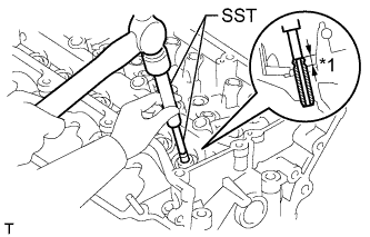
Text in Illustration *1 Protrusion Height Using SST, tap in the intake valve guide bushes to the specified protrusion height.
- SST
- 09201-10000 ( 09201-01050 )
- 09950-70010 ( 09951-07100 )
Protrusion height 9.10 to 9.90 mm (0.358 to 0.390 in.) -
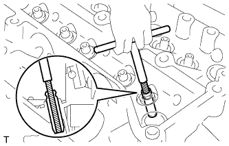
Using a sharp 5.5 mm reamer, ream the valve guide bushes to obtain the specified clearance.
Standard oil clearance 0.025 to 0.060 mm (0.000984 to 0.00236 in.)
-
-
REPLACE EXHAUST VALVE GUIDE BUSH
-
Heat the cylinder head to 80 to 100°C (176 to 212°F).
-
Place the cylinder head on wooden blocks.
-
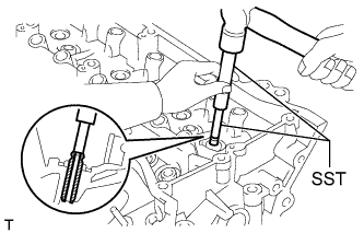
Using SST and a hammer, tap out the exhaust valve guide bushes.
- SST
- 09201-10000 ( 09201-01050 )
- 09950-70010 ( 09951-07100 )
-
Using a caliper gauge, measure the exhaust valve guide bush bore diameter of the cylinder head.
Standard Bush Bore Diameter Item Specified Condition STD 10.285 to 10.306 mm (0.4049 to 0.4057 in.) O/S 0.05 10.335 to 10.356 mm (0.4069 to 0.4077 in.) -
Select a new valve guide bush.
New Guide Bush Item Specified Condition Bush Bore Diameter 10.285 to 10.306 mm (0.4049 to 0.4057 in.) 10.335 to 10.356 mm (0.4069 to 0.4077 in.) Use Bush STD O/S 0.05 If the bush bore diameter of the cylinder head is more than 10.306 mm (0.4057 in.), machine the bush bore diameter to 10.335 to 10.356 mm (0.4069 to 0.4077 in.) to install an O/S 0.05 valve guide bush.
If the bush bore diameter of the cylinder head is more than 10.356 mm (0.4077 in.), replace the cylinder head.
New Guide Bush Diameter Item Specified Condition STD 10.333 to 10.344 mm (0.4068 to 0.4072 in.) O/S 0.05 10.383 to 10.394 mm (0.4088 to 0.4092 in.) Tech Tips
Different bushes are used for the intake and exhaust.
Standard bush length 46.8 to 47.2 mm (1.84 to 1.86 in.) -
Heat the cylinder head to 80 to 100°C (176 to 212°F).
-
Place the cylinder head on wooden blocks.
-
Text in Illustration *1 Protrusion Height Using SST, tap in the exhaust valve guide bushes to the specified protrusion height.
- SST
- 09201-10000 ( 09201-01050 )
- 09950-70010 ( 09951-07100 )
Protrusion height 9.10 to 9.90 mm (0.358 to 0.390 in.) -
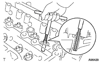
Using a sharp 5.5 mm reamer, ream the valve guide bushes to obtain the specified clearance.
Standard oil clearance 0.030 to 0.065 mm (0.00118 to 0.00256 in.)
-
-
REPLACE UNION
-
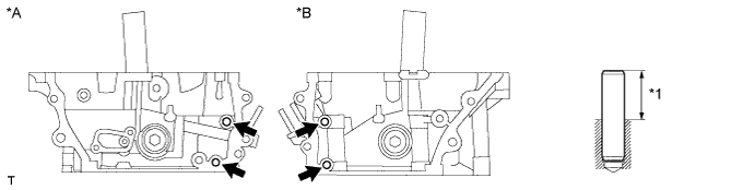
Remove the union from the bank 1 cylinder head (front side) and bank 2 cylinder head (intake port side).
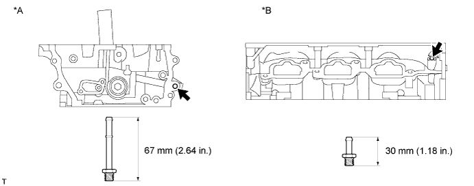
Text in Illustration *A Front Side of RH *B Intake Side of LH -
Apply adhesive to 2 or 3 threads of the bolt ends of new unions.
Adhesive Toyota Genuine Adhesive 1324, Three Bond 1324 or equivalent -
Using a 12 mm deep socket wrench, install the 2 unions.
- Torque:
- 15 N*m { 150 kgf*cm, 11 ft.*lbf }
-
-
REPLACE TIGHT PLUG
Note
If coolant leaks from a tight plug or a plug is corroded, replace it.
-
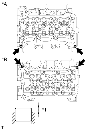
Remove the tight plugs.
-
Apply adhesive around new tight plugs.
Adhesive Toyota Genuine Adhesive 1324, Three Bond 1324 or equivalent -
Using SST and a hammer, tap in the tight plugs to the standard depth.
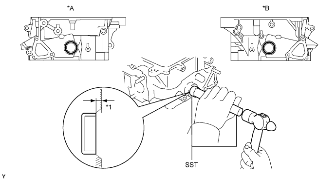
- SST
- 09950-60010 ( 09951-00250 )
- 09950-70010 ( 09951-07150 )
Standard depth 1.7 to 2.7 mm (0.0669 to 0.106 in.) Text in Illustration *A RH *B LH *1 Standard Depth - -
-
-
REPLACE STRAIGHT PIN
Note
If a straight pin is deformed, replace it.
-
Using a plastic-faced hammer, tap in new straight pins as shown in the illustration.
Protrusion height 18.0 to 19.0 mm (0.708 to 0.748 in.) Text in Illustration *A RH *B LH *1 Protrusion Height - -
-
-
REPLACE RING PIN
Note
It is not necessary to remove a ring pin unless it is being replaced.
-
Text in Illustration *A RH *B LH *1 Protrusion Height Using a plastic-faced hammer, tap in new ring pins to the specified protrusion height.
Protrusion height 2.5 to 3.5 mm (0.0984 to 0.138 in.)
-
-
REPLACE SPARK PLUG TUBE
Text in Illustration *1 Adhesive *2 Distance Tech Tips
When using a new cylinder head, the spark plug tubes must be replaced.
-
Remove the spark plug tube.
-
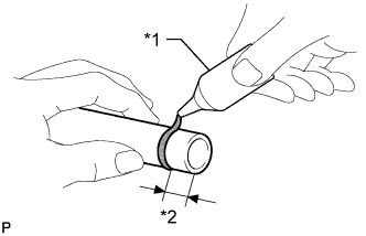
Apply adhesive to the end of a new spark plug tube.
Adhesive Toyota Genuine Adhesive 1324, Three Bond 1324 or equivalent. Standard seal diameter 1.0 to 3.0 mm (0.394 to 0.118 in.) Distance 9.0 to 15.0 mm (0.354 to 0.590 in.) Note
-
Be careful not to deform the spark plug tube.
-
Be careful not to expose the seal to coolant for at least 1 hour after installing it.
-
-
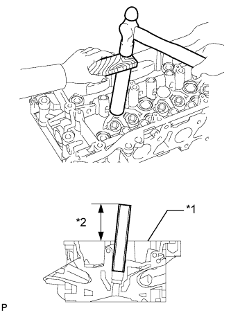
Text in Illustration *1 Cylinder Head Top Surface *2 Protrusion Height Using a wooden block and hammer, tap in the spark plug tube to the specified protrusion height.
Standard protrusion height 75.1 to 76.1 mm (2.96 to 3.00 in.) Note
To avoid tapping in the spark plug tube too far, measure the protrusion height while tapping it.
-