ENGINE UNIT REASSEMBLY

-
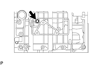
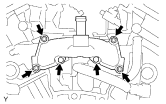
INSTALL STUD BOLT
-
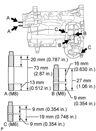
Install the oil pan stud bolt.
-
Using E6 and E8 "TORX" socket wrenches, install the 6 stud bolts as shown in the illustration.
- Torque:
- for stud bolt A
- 10 N*m { 102 kgf*cm, 7 ft.*lbf }
- for stud bolt B and C
- 4.0 N*m { 41 kgf*cm, 35 in.*lbf }
-
-
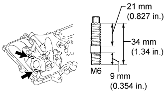
Install the cylinder head cover LH stud bolt.
-
Using an E6 "TORX" socket wrench, install the stud bolt as shown in the illustration.
- Torque:
- 4.0 N*m { 41 kgf*cm, 35 in.*lbf }
-
-
-
INSTALL RING PIN
-
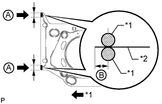
Using a plastic-faced hammer, tap in new ring pins to the camshaft housing.
Standard protrusion height 2.7 to 3.3 mm (0.106 to 0.130 in.) 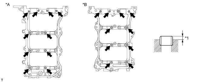
Text in Illustration *A LH *B RH *1 Protrusion Height - -
-
-
INSTALL STRAIGHT PIN
-
Using a plastic-faced hammer, tap in new straight pins to the camshaft housing.
Standard Protrusion Height Item Specified Condition Ring pin A 7.7 to 8.3 mm (0.303 to 0.327 in.) Ring pin B 5.7 to 6.3 mm (0.224 to 0.248 in.) 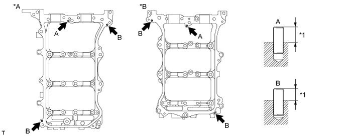
Text in Illustration *A LH *B RH *1 Protrusion Height - -
-
-
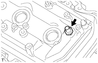
INSTALL TAPER SCREW PLUG
-
Apply adhesive to 2 or 3 threads of the taper screw plug end.
Adhesive Toyota Genuine Adhesive 1324, Three Bond 1324 or equivalent -
Install the taper screw plug.
- Torque:
- 30 N*m { 306 kgf*cm, 22 ft.*lbf }
Note
-
Install the taper screw plug within 3 minutes after applying adhesive.
-
Do not expose the taper screw plug to coolant within 1 hour of the installation.
-
-
INSTALL REAR CRANKSHAFT OIL SEAL
-
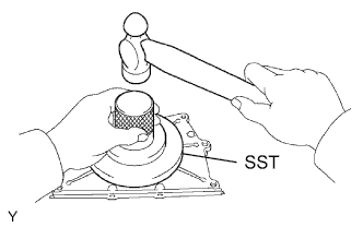
Using SST and a hammer, tap in a new oil seal until its surface is flush with the rear oil seal retainer edge.
- SST
- 09223-78010
-
Apply MP grease to the lip of the oil seal.
-
-
INSTALL ENGINE REAR OIL SEAL RETAINER
-
Remove any old packing (FIPG) material and be careful not to drop any oil on the contact surfaces of the oil seal retainer or cylinder block.
-
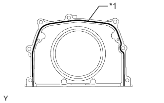
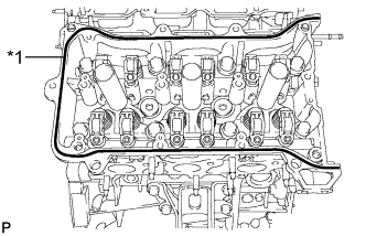
Text in Illustration *1 Seal Packing Apply seal packing in a continuous line as shown in the illustration.
Seal packing Toyota Genuine Seal Packing Black, Three Bond 1207B or equivalent Standard seal diameter 2 to 3 mm (0.0787 to 0.118 in.) Note
-
Remove any oil from the contact surfaces.
-
Install the oil seal retainer within 3 minutes after applying seal packing.
-
-
Install the oil seal retainer with the 5 bolts and 2 nuts.
- Torque:
- 10 N*m { 102 kgf*cm, 7 ft.*lbf }
Note
-
When installing the oil seal retainer, make sure the lip of the oil seal is not damaged.
-
When installing the oil seal retainer, make sure the lip of the oil seal is not folded incorrectly.
-
Do not start the engine for at least 2 hours after installation.
-
-
INSTALL CYLINDER BLOCK WATER JACKET SPACER
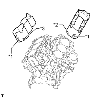
Text in Illustration *1 UP Mark *2 L Mark *3 R Mark
-
Install the 2 water jacket spacers as shown in the illustration.
Note
Make sure that face the "L mark", "R mark" and "UP mark" are oriented as shown in the illustration.
-
-
INSTALL KNOCK SENSOR
-
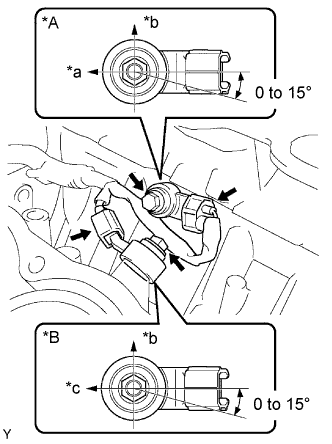
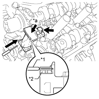
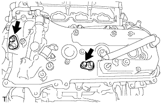
Text in Illustration *A for Bank 2 *B for Bank 1 *a Engine Rear *b Top *c Engine Front Install the 2 sensors with the 2 bolts as shown in the illustration.
- Torque:
- 20 N*m { 204 kgf*cm, 15 ft.*lbf }
-
Connect the 2 sensor connectors.
-
-
INSTALL NO. 1 WATER OUTLET PIPE
-
Install the water outlet pipe with the 2 nuts and bolt.
- Torque:
- 10 N*m { 102 kgf*cm, 7 ft.*lbf }
-
Attach the 3 wire harness clamps.
-
-
INSTALL CYLINDER HEAD GASKET
-
Remove any old packing (FIPG) material and be careful not to drop any oil on the contact surfaces of the cylinder head or cylinder block.
-
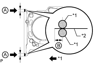
Text in Illustration *1 Seal Packing *2 Gasket Apply seal packing to a new cylinder head gasket as shown in the illustration.
Seal packing Toyota Genuine Seal Packing Black, Three Bond 1207B or equivalent Standard seal diameter 2.5 to 3.0 mm (0.0984 to 0.118 in.) Seal Packing Application Range A 10 to 15 mm (0.394 to 0.591 in.) B 1.25 to 1.5 mm (0.0492 to 0.0591 in.) Note
-
Remove any oil from the contact surface.
-
Install the cylinder head gasket within 3 minutes and tighten the bolts within 15 minutes after applying seal packing.
-
Do not add engine oil within 2 hours of installation.
-
-
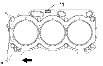
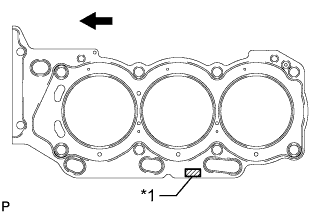
Text in Illustration *1 Lot No. 
Engine Front Place the cylinder head gasket on the cylinder block surface with the front face of the Lot No. stamp upward.
Note
Make sure that the gasket is installed facing the proper direction.
-
-
INSTALL CYLINDER HEAD SUB-ASSEMBLY
-
Place the cylinder head on the cylinder block.
Note
-
Gently place the cylinder head in order not to damage the gasket with the bottom part of the head.
-
Make sure that no oil is on the mounting surface of the cylinder head.
Tech Tips
The cylinder head bolts are tightened in 3 progressive steps.
-
-
Apply a light coat of engine oil to the threads and under the heads of the cylinder head bolts.
-
Step 1:
-
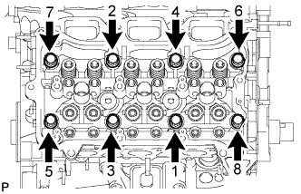
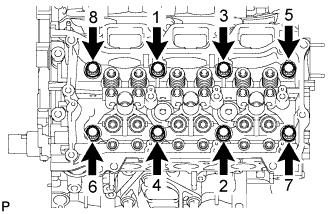
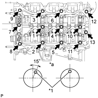
Using a 10 mm bi-hexagon wrench, install and uniformly tighten the 8 cylinder head bolts with the plate washers in several steps in the sequence shown in the illustration.
- Torque:
- 36 N*m { 367 kgf*cm, 27 ft.*lbf }
-
-
Step 2:
-
Mark the front side of each cylinder head bolt head with paint.
-
Tighten the cylinder head bolts another 90°.
-
-
Step 3:
-
Tighten the cylinder head bolts an additional 90°.
-
Check that the paint mark is now at a 180° angle to the front.
Note
Thoroughly wipe clean any seal packing.
-
-
-
INSTALL NO. 2 CYLINDER HEAD GASKET
-
Remove any old packing (FIPG) material and be careful not to drop any oil on the contact surfaces of the cylinder head or cylinder block.
-
Text in Illustration *1 Seal Packing *2 Gasket Apply seal packing to a new cylinder head gasket as shown in the illustration.
Seal packing Toyota Genuine Seal Packing Black, Three Bond 1207B or equivalent Standard seal diameter 2.5 to 3.0 mm (0.0984 to 0.118 in.) Seal Packing Application Range A 10 to 15 mm (0.394 to 0.591 in.) B 1.25 to 1.5 mm (0.0492 to 0.0591 in.) Note
-
Remove any oil from the contact surface.
-
Install the cylinder head gasket within 3 minutes and tighten the bolts within 15 minutes after applying seal packing.
-
Do not add engine oil within 2 hours of installation.
-
-
Text in Illustration *1 Lot No. Engine Front Place the cylinder head gasket on the cylinder block surface with the front face of the Lot No. stamp upward.
Note
Make sure that the gasket is installed facing the proper direction.
-
-
INSTALL CYLINDER HEAD LH
-
Place the cylinder head on the cylinder block.
Note
-
Gently place the cylinder head in order not to damage the gasket with the bottom part of the head.
-
Make sure that no oil is on the mounting surface of the cylinder head.
Tech Tips
The cylinder head bolts are tightened in 3 progressive steps.
-
-
Apply a light coat of engine oil to the threads and under the heads of the cylinder head bolts.
-
Step 1:
-
Using a 10 mm bi-hexagon wrench, install and uniformly tighten the 8 cylinder head bolts with the plate washers in several steps in the sequence shown in the illustration.
- Torque:
- 36 N*m { 367 kgf*cm, 27 ft.*lbf }
-
-
Step 2:
-
Mark the front side of each cylinder head bolt head with paint.
-
Tighten the cylinder head bolts another 90°.
-
-
Step 3:
-
Tighten the cylinder head bolts an additional 90°.
-
Check that the paint mark is now at a 180° angle to the front.
-
-
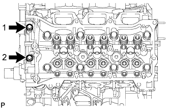
Tighten the 2 bolts in the order shown in the illustration.
- Torque:
- 30 N*m { 306 kgf*cm, 22 ft.*lbf }
Note
Thoroughly wipe clean any seal packing.
-
-
INSTALL VALVE STEM CAP
-
Apply a light coat of engine oil to the valve stem caps.
-
Install the 24 valve stem caps to the cylinder head.
-
-
INSTALL VALVE LASH ADJUSTER ASSEMBLY
-
Inspect the valve lash adjuster Click here.
-
Install the 24 valve lash adjusters to the cylinder head.
Note
Install the lash adjuster at the same place it was removed from.
-
-
INSTALL NO. 1 VALVE ROCKER ARM SUB-ASSEMBLY
-
Apply engine oil to the lash adjuster tips and valve stem cap ends.
-
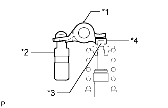
Text in Illustration *1 Valve Rocker Arm *2 Lash Adjuster *3 Valve Stem *4 Valve Stem Cap Install the 24 valve rocker arms as shown in the illustration.
-
-
INSTALL CAMSHAFT BEARING CAP (for Bank 2)
-
Apply a light coat of engine oil to the camshaft journals, camshaft housings and bearing caps.
-
Install the No. 3 camshaft and No. 4 camshaft to the camshaft housing.
-
Check the marks and numbers on the camshaft bearing caps and place each of them in the proper position facing the proper direction.
-
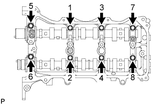
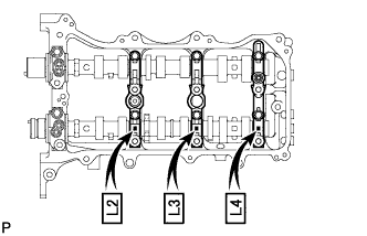
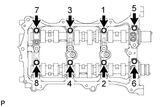
Temporarily install the 8 bolts in the order shown in the illustration.
- Torque:
- 10 N*m { 102 kgf*cm, 7 ft.*lbf }
-
-
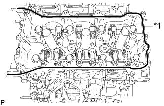
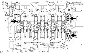
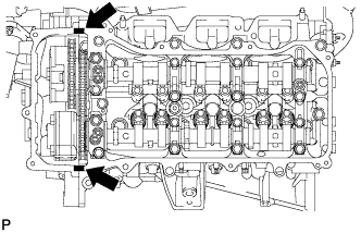
INSTALL CAMSHAFT HOUSING SUB-ASSEMBLY LH
-
Text in Illustration *1 Valve Rocker Arm *2 Lash Adjuster *3 Valve Stem *4 Valve Stem Cap Make sure that the valve rocker arm is installed as shown in the illustration.
-
Text in Illustration *1 Seal Packing Apply seal packing in a continuous line as shown in the illustration.
Seal packing Toyota Genuine Seal Packing Black, Three Bond 1207B or equivalent Seal diameter 3.5 to 4.5 mm (0.138 to 0.177 in.) Note
-
Remove any oil from the contact surface.
-
Install the camshaft housing within 3 minutes and tighten the bolts within 15 minutes after applying seal packing.
-
-
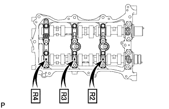
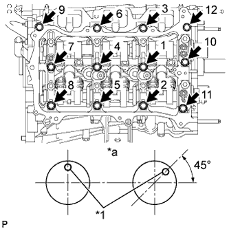
Text in Illustration *1 Knock Pin *a Front View Install the camshaft housing sub-assembly LH and tighten the 13 bolts in the order shown in the illustration.
- Torque:
- 28 N*m { 286 kgf*cm, 21 ft.*lbf }
Note
-
When installing the camshaft housing sub-assembly LH, it is necessary to correctly position the camshafts as shown in the illustration. Failure to correctly position these parts may result in damage due to contact between the pistons and valves. If a camshaft is rotated with a piston at TDC, valve contact will occur.
-
If any of the bolts are loosened during installation, remove the camshaft housing sub-assembly LH, clean the installation surfaces and reapply seal packing.
-
If the camshaft housing sub-assembly LH is removed because any of the bolts are loosened during installation, make sure that the previously applied seal packing does not enter any oil passages.
-
Do not start the engine for at least 2 hours after installing.
-
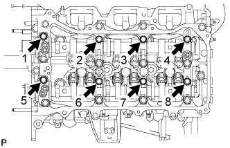
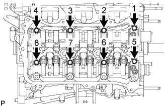
Tighten the 8 bolts in the order shown in the illustration.
- Torque:
- 16 N*m { 163 kgf*cm, 12 ft.*lbf }
Note
Thoroughly wipe clean any seal packing.
-
-
INSTALL CAMSHAFT BEARING CAP (for Bank 1)
-
Apply a light coat of engine oil to the camshaft journals, camshaft housings and bearing caps.
-
Install the camshaft and No. 2 camshaft to the camshaft housing.
-
Check the marks and numbers on the camshaft bearing caps and place each of them in the proper position facing the proper direction.
-
Temporarily install the 8 bearing cap bolts in the order shown in the illustration.
- Torque:
- 10 N*m { 102 kgf*cm, 7 ft.*lbf }
-
-
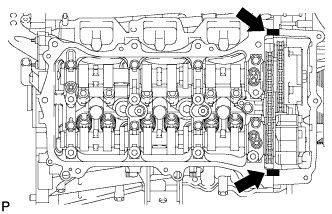
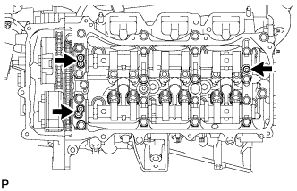
INSTALL CAMSHAFT HOUSING SUB-ASSEMBLY RH
-
Text in Illustration *1 Valve Rocker Arm *2 Lash Adjuster *3 Valve Stem *4 Valve Stem Cap Make sure that the No. 1 valve rocker arm sub-assembly is installed as shown in the illustration.
-
Text in Illustration *1 Seal Packing Apply seal packing in a continuous line as shown in the illustration.
Seal packing Toyota Genuine Seal Packing Black, Three Bond 1207B or equivalent Seal diameter 3.5 to 4.5 mm (0.138 to 0.177 in.) Note
-
Remove any oil from the contact surface.
-
Install the camshaft housing within 3 minutes and tighten the bolts within 15 minutes after applying seal packing.
-
-
Text in Illustration *1 Knock Pin *a Front View Install the camshaft housing sub-assembly RH and tighten the 12 bolts in the order shown in the illustration.
- Torque:
- 28 N*m { 286 kgf*cm, 21 ft.*lbf }
Note
-
When installing the camshaft housing RH, it is necessary to correctly position the camshafts as shown in the illustration.
Failure to correctly position these parts may result in damage due to contact between the pistons and valves. If a camshaft is rotated with a piston at TDC, valve contact will occur.
-
If any of the bolts are loosened during installation, remove the camshaft housing sub-assembly RH, clean the installation surfaces and reapply seal packing.
-
If the camshaft housing sub-assembly RH is removed because any of the bolts are loosened during installation, make sure that the previously applied seal packing does not enter any oil passages.
-
Do not start the engine for at least 2 hours after installing.
-
Tighten the 8 bolts in the order shown in the illustration.
- Torque:
- 16 N*m { 163 kgf*cm, 12 ft.*lbf }
Note
Thoroughly wipe clean any seal packing.
-
-
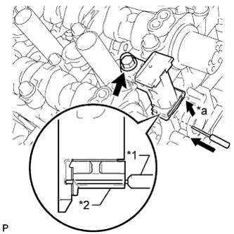
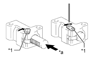
INSTALL NO. 3 CHAIN TENSIONER ASSEMBLY (for Bank 2)
-
Text in Illustration *1 Pin *2 Plunger *a Push Install the No. 3 chain tensioner assembly with the bolt.
- Torque:
- 21 N*m { 214 kgf*cm, 15 ft.*lbf }
-
Push in the tensioner and insert a pin with a diameter of 1.0 mm (0.0394 in.) into the hole to hold the tensioner.
-
-
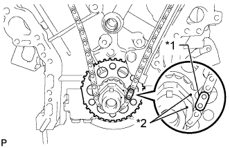
INSTALL CAMSHAFT TIMING GEARS AND NO. 2 CHAIN (for Bank 2)
-
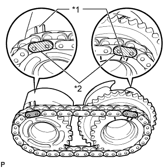
Text in Illustration *1 Timing Mark *2 Mark Plate Align the mark plates (yellow) with the timing marks of the camshaft timing gear assemblies as shown in the illustration.
-
Apply a light coat of engine oil to the bolt threads and bolt-seating surface.
-
Align the knock pin of the camshaft with the pin hole of the camshaft timing gear assembly. Install the camshaft timing gear assembly and camshaft timing exhaust gear LH with the No. 2 chain sub-assembly installed.
-
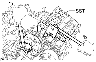
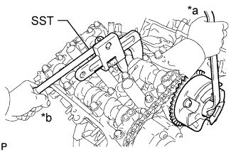
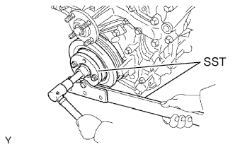
Text in Illustration *a Turn *b Hold Using SST to hold the hexagonal portion of each camshaft, tighten the bolts of the camshaft timing gear assembly and camshaft timing exhaust gear assembly.
- SST
- 09922-10010
- Torque:
- 100 N*m { 1020 kgf*cm, 74 ft.*lbf }
-
Remove the pin from the No. 3 chain tensioner assembly.
-
-
INSTALL NO. 2 CHAIN TENSIONER ASSEMBLY (for Bank 1)
-
Text in Illustration *1 Pin *2 Plunger *a Push Install the No. 2 chain tensioner assembly with the bolt.
- Torque:
- 21 N*m { 214 kgf*cm, 15 ft.*lbf }
-
Push in the No. 2 chain tensioner assembly and insert a pin with a diameter of 1.0 mm (0.0394 in.) into the hole to hold the tensioner.
-
-
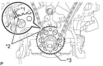
INSTALL CAMSHAFT TIMING GEARS AND NO. 2 CHAIN (for Bank 1)
-
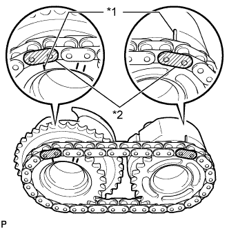
Text in Illustration *1 Timing Mark *2 Mark Plate Align the mark plates (yellow) with the timing marks of the camshaft timing gear assemblies as shown in the illustration.
-
Apply a light coat of engine oil to the bolt threads and bolt-seating surface.
-
Align the knock pin of the camshaft with the pin hole of the camshaft timing gear assembly. Install the camshaft timing gear assembly and camshaft timing exhaust gear assembly with the No. 2 chain sub-assembly installed.
-
Text in Illustration *a Turn *b Hold Using SST to hold the hexagonal portion of each camshaft, tighten the bolts of the camshaft timing gear assembly and camshaft timing exhaust gear assembly.
- SST
- 09922-10010
- Torque:
- 100 N*m { 1020 kgf*cm, 74 ft.*lbf }
-
Remove the pin from the No. 2 chain tensioner assembly.
-
-
INSTALL NO. 1 CHAIN VIBRATION DAMPER
-
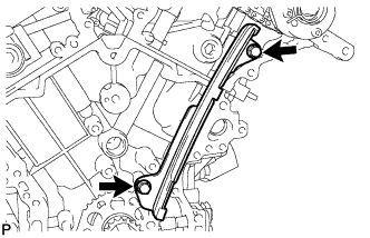
Install the No. 1 chain vibration damper with the 2 bolts.
- Torque:
- 23 N*m { 229 kgf*cm, 17 ft.*lbf }
-
-
INSTALL NO. 2 CHAIN VIBRATION DAMPER
-
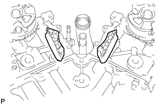
Install the 2 No. 2 chain vibration dampers.
-
-
INSTALL CRANKSHAFT TIMING SPROCKET
-
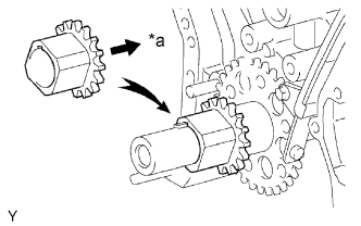
Text in Illustration *a Inward Align the key groove of the timing sprocket with the timing sprocket set key.
-
Install the timing sprocket to the crankshaft with the sprocket facing inward as shown in the illustration.
-
-
INSTALL NO. 1 IDLE GEAR SHAFT
-
Apply a light coat of engine oil to the sliding surface of the No. 1 idle gear shaft.
-
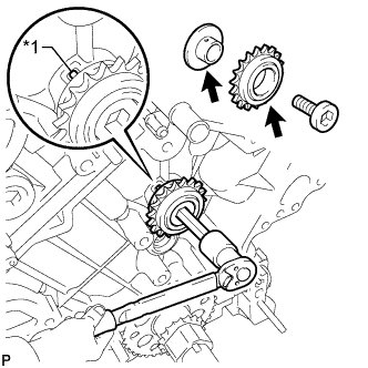
Text in Illustration *1 Knock Pin Temporarily install the No. 1 idle gear shaft and No. 1 idle gear with the No. 2 idle gear shaft while aligning the knock pin of the No. 1 idle gear shaft with the knock pin groove of the cylinder block.
Note
Make sure that the idle gear is installed facing the proper direction.
-
Using a 10 mm hexagon wrench, tighten the No. 2 idle gear shaft.
- Torque:
- 60 N*m { 612 kgf*cm, 44 ft.*lbf }
-
Remove the bar from the chain tensioner.
-
-
INSTALL NO. 1 CHAIN SUB-ASSEMBLY
-
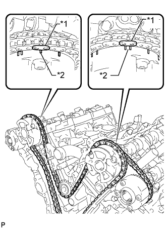
Text in Illustration *1 Mark Plate *2 Timing Mark Align the mark plate and timing marks as shown in the illustration and install the chain.
Tech Tips
The camshaft mark plates are orange.
-
Do not pass the chain around the crankshaft, just temporarily place it on the crankshaft.
-
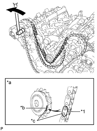
Text in Illustration *1 Chain Plate *a When idle sprocket is reused *b Mark *c Align 
Turn Turn the camshaft timing gear assembly on bank 1 counterclockwise to tighten the chain between the banks.
Note
When the idle sprocket assembly is reused, align the chain plate with the mark where the plate had been when tightening the chain between the banks.
-
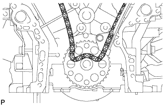
Text in Illustration *1 Mark Plate *2 Timing Mark Align the mark plate and timing marks as shown in the illustration and install the chain to the crankshaft timing sprocket.
Tech Tips
The crankshaft mark plate is yellow.
-
Temporarily install the pulley set bolt.
-
Text in Illustration *1 Center Line *2 Timing Mark *3 Sensor Plate Turn the crankshaft clockwise to set it to the RH block bore center line (TDC/compression).
-
-
INSTALL CHAIN TENSIONER SLIPPER
-
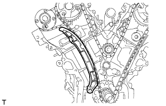
Install the chain tensioner slipper.
-
-
INSTALL NO. 1 CHAIN TENSIONER ASSEMBLY
-
Text in Illustration *1 Stopper Plate *a Push Turn the stopper plate of the tensioner clockwise and push in the plunger of the tensioner as shown in the illustration.
-
Turn the stopper plate of the tensioner counterclockwise and insert a pin of φ1.27 mm (0.0500 in.) into the holes on the stopper plate and tensioner to fix the stopper plate in place.
-

Install the chain tensioner with the 2 bolts.
- Torque:
- 10 N*m { 102 kgf*cm, 7 ft.*lbf }
-
Remove the pin from the No. 1 chain tensioner.
-
-
INSPECT VALVE TIMING
-
Check the camshaft timing marks.
Note
-
Check each timing mark from a viewpoint directly in line with the center of the camshaft and the timing mark on each camshaft timing gear.
-
If the timing marks are checked from any other viewpoint, the valve timing may appear misaligned.
-
-
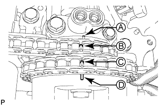
Check that each camshaft timing mark is positioned as shown in the illustration.
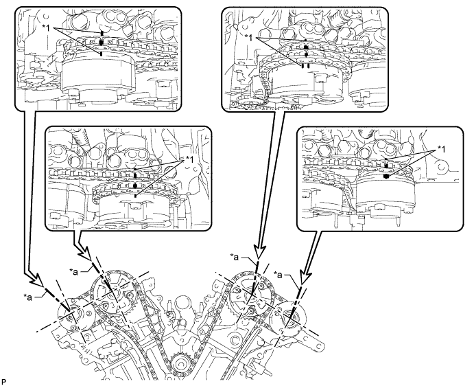
Text in Illustration *1 Timing Mark - - *a Viewpoint - - Tech Tips
for Intake Camshaft:
Be sure to check mark A at the point when marks B, C and D are positioned in line. If the marks are checked from any other viewpoint, they cannot be checked correctly.
-
If the valve timing is misaligned, reinstall the timing chain.
-
Remove the pulley set bolt.
-
-
INSTALL FRONT CRANKSHAFT OIL SEAL
-
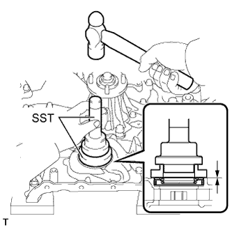
Using SST and a hammer, tap in a new oil seal until its surface is flush with the timing chain cover edge.
- SST
- 09223-22010
- 09506-35010
Note
-
Keep the lip free from foreign matter.
-
Do not tap on the oil seal at an angle.
-
Make sure that the oil seal edge does not protrude from the timing chain case.
-
-
INSTALL WATER PUMP ASSEMBLY
-
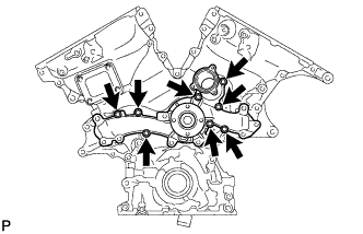
Install a new gasket and the water pump with the 8 bolts.
- Torque:
- 11 N*m { 112 kgf*cm, 8 ft.*lbf }
-
-
INSTALL TIMING CHAIN COVER SUB-ASSEMBLY
-
Remove any old packing (FIPG material) and be careful not to drop any oil on the contact surfaces of the timing chain cover, cylinder head and cylinder block.
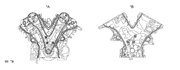
Text in Illustration *A Cylinder head and cylinder block side *B Timing chain cover side *a Clean and degrease - - Note
Be sure to clean and degrease the contact surfaces, especially the surfaces indicated in the illustration.
-
Apply a light coat of engine oil to a new oil pump gasket.
-
Install the oil pump gasket.
-
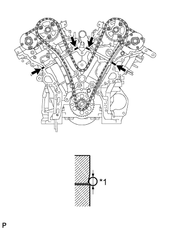
Text in Illustration *1 Seal Diameter Seal Packing Apply seal packing as shown in the illustration.
Seal packing Toyota Genuine Seal Packing Black, Three Bond 1207B or equivalent Standard seal diameter 3.0 to 4.0 mm (0.118 to 0.157 in.) -
Apply seal packing to the timing chain cover in a continuous line as shown in the following illustration.
Seal packing Toyota Genuine Seal Packing Black, Three Bond 1207B or equivalent Toyota Genuine Seal Packing 1282B, Three Bond 1282B or equivalent 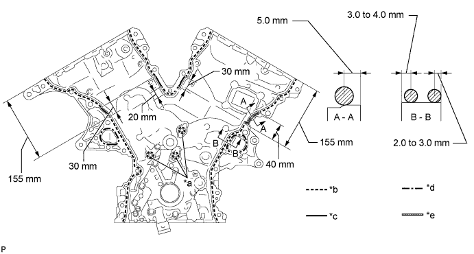
Text in Illustration *a Be sure to apply seal packing *b Dashed line area (Seal packing: Toyota Genuine Seal Packing Black, Three Bond 1207B or equivalent) *c Continuous line area (Seal packing: Toyota Genuine Seal Packing Black, Three Bond 1207B or equivalent) *d Alternate long and short dashed line area (Seal packing: Toyota Genuine Seal Packing 1282B, Three Bond 1282B or equivalent) *e Diagonal line area (Seal packing: Toyota Genuine Seal Packing Black, Three Bond 1207B or equivalent) - - Note
-
When the contact surfaces are wet, wipe them with an oil-free cloth before applying seal packing.
-
Install the chain cover within 3 minutes and tighten the bolts within 10 minutes after applying seal packing.
Application Specification Area Seal Packing Diameter Application Position from Inside Seal Line Continuous Line Area 4.5 mm (0.177 in.) or more 3.0 to 4.0 mm (0.118 to 0.158 in.) Alternate Long and Short Dashed Line Area 3.5 mm (0.138 in.) or more 2.0 to 3.0 mm (0.0787 to 0.118 in.) Dashed Line Area 3.5 mm (0.138 in.) or more 3.0 to 4.0 mm (0.118 to 0.158 in.) Diagonal Line Area 6.0 mm (0.236 in.) or more 5.0 mm (0.197 in.) -
-
Text in Illustration *1 Drive Rotor Spline *2 Crankshaft Align the oil pump drive rotor spline and crankshaft as shown in the illustration. Install the drive rotor and chain cover to the crankshaft.
-
Install the timing chain cover with the 26 bolts, labeled A, B, C and D, and the 2 nuts. Tighten the bolts and nuts uniformly in several steps.
Standard Bolt Item Length Bolt A 25 mm (0.984 in.) Bolt B 55 mm (2.17 in.) Bolt C 35 mm (1.38 in.) Bolt D 65 mm (2.56 in.) 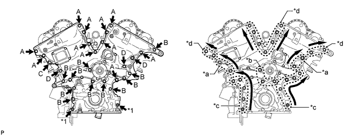
Text in Illustration *1 Nut - - *a Area 1 *b Area 2 *c Area 3 *d Area 4 Note
Make sure that there is no oil on the bolt threads.
-
Tighten the bolts in area 1.
- Torque:
- 47 N*m { 479 kgf*cm, 35 ft.*lbf }
Tech Tips
Tighten the bolts from bottom to top as shown in the illustration.
-
Tighten the bolts in area 2.
- Torque:
- 23 N*m { 235 kgf*cm, 17 ft.*lbf }
-
Tighten the bolts in area 3.
- Torque:
- 23 N*m { 235 kgf*cm, 17 ft.*lbf }
Tech Tips
Tighten the bolts and nuts from top to bottom as shown in the illustration.
-
Tighten the bolts in area 4.
- Torque:
- 23 N*m { 235 kgf*cm, 17 ft.*lbf }
Tech Tips
Tighten the bolts from bottom to top as shown in the illustration.
Note
-
Do not start the engine for at least 2 hours after installation.
-
Wipe off any seal packing that seeped out around the surfaces of the oil pan and head cover and make sure that there is no seal packing seeping out around the edges.
-
-
INSTALL NO. 1 OIL PAN BAFFLE PLATE
-
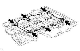
Install the No. 1 oil pan baffle plate with the 6 bolts.
- Torque:
- 10 N*m { 102 kgf*cm, 7 ft.*lbf }
-
-
INSTALL OIL PAN SUB-ASSEMBLY
-
Remove any old packing (FIPG material) and be careful not to drop any oil on the contact surfaces of the cylinder block, rear oil seal retainer and oil pan.
-
Install a new 3 O-rings to the timing chain cover.
-
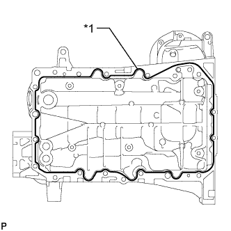
Text in Illustration *1 Seal Packing Apply seal packing in a continuous line as shown in the illustration.
Seal packing Toyota Genuine Seal Packing Black, Three Bond 1207B or equivalent Standard seal diameter 3.0 to 4.0 mm (0.118 to 0.157 in.) Note
-
Remove any oil from the contact surface.
-
Install the oil pan within 3 minutes after applying seal packing.
-
-
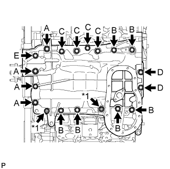
Text in Illustration *1 Nut Install the oil pan with the 17 bolts (A, B, C, D and E) and 2 nuts. Tighten the bolts and nuts uniformly in several steps.
- Torque:
- for bolt A, B, C and E, and nut
- 21 N*m { 214 kgf*cm, 15 ft.*lbf }
- for bolt D
- 10 N*m { 102 kgf*cm, 7 ft.*lbf }
Standard Bolt Item Length Bolt A 60 mm (2.36 in.) Bolt B 45 mm (1.77 in.) Bolt C 25 mm (0.984 in.) Bolt D 16 mm (0.630 in.) Bolt E 70 mm (2.76 in.) Note
Do not start the engine for at least 2 hours after installing.
-
-
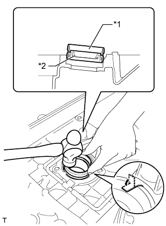
INSTALL OIL STRAINER SUB-ASSEMBLY
-
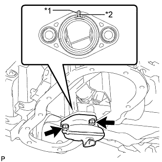
Text in Illustration *1 Groove *2 Protrusion Install a new gasket to the oil strainer.
Tech Tips
Align the protrusion of the gasket with the groove of the oil strainer.
-
Install the oil strainer with the 2 nuts.
- Torque:
- 9.0 N*m { 92 kgf*cm, 80 in.*lbf }
-
-
INSTALL NO. 2 OIL PAN SUB-ASSEMBLY
-
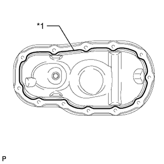
Text in Illustration *1 Seal Packing Apply seal packing in a continuous line as shown in the illustration.
Seal packing Toyota Genuine Seal Packing Black, Three Bond 1207B or equivalent Standard seal diameter 3.0 to 4.0 mm (0.118 to 0.157 in.) Note
-
Remove any oil from the contact surface.
-
Install the No. 2 oil pan within 3 minutes after applying seal packing.
-
-
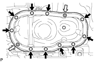
Install the No. 2 oil pan with the 10 bolts and 2 nuts. Tighten the bolts and nuts uniformly in several steps.
- Torque:
- 10 N*m { 102 kgf*cm, 7 ft.*lbf }
Text in Illustration Bolt 
Nut Note
-
Tighten the nuts first. After tightening the bolts, check that the nuts and bolts are tightened to the specified torque.
-
Do not start the engine for at least 2 hours after the installation.
-
-
INSTALL OIL PAN DRAIN PLUG
-
Install a new gasket and the drain plug.
- Torque:
- 40 N*m { 408 kgf*cm, 30 ft.*lbf }
-
-
INSTALL ENGINE OIL LEVEL SENSOR (w/ Warmer)
-
Install a new gasket to the engine oil level sensor.
-
Install the sensor with the 4 bolts.
- Torque:
- 10 N*m { 102 kgf*cm, 7 ft.*lbf }
-
Connect the connector.
-
-
POUR ENGINE OIL
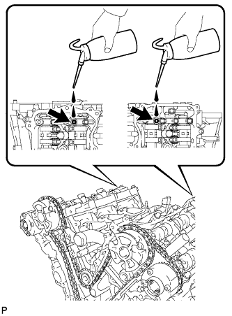
Tech Tips
Before installing the cylinder head cover, pour engine oil into the locations shown in the illustration.
-
INSTALL SPARK PLUG TUBE GASKET
-
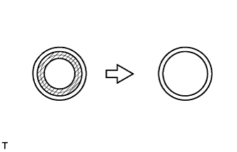
Using a cutter knife, cut off the seal part of the removed gasket.
Text in Illustration 
Area to cut off -
Text in Illustration *1 Removed Gasket *2 New Gasket Using the removed gasket and a hammer, tap in a new gasket until it stops.
Tech Tips
If the removed gasket does not fit on the new one, correct the removed one with pliers.
-
Apply a light coat of MP grease to the gasket lip.
-
Return the ventilation baffle plate claws to their original positions.
-
-
INSTALL CYLINDER HEAD COVER SUB-ASSEMBLY
-
Remove any old packing (FIPG) material and be careful not to drop any oil on the contact surfaces of the cylinder head, timing chain cover or cylinder head cover.
-
Apply seal packing as shown in the illustration.
Seal packing Toyota Genuine Seal Packing Black, Three Bond 1207B or equivalent Standard seal diameter 2 to 3 mm (0.0787 to 0.118 in.) Text in Illustration Seal Packing Note
-
Remove any oil from the contact surface.
-
Install the cylinder head cover within 3 minutes and tighten the bolts within 15 minutes after applying seal packing.
-
-
Install 3 new gaskets as shown in the illustration.
-
Install a new gasket to the cylinder head cover.
-
Install the seal washers to the bolts.
-
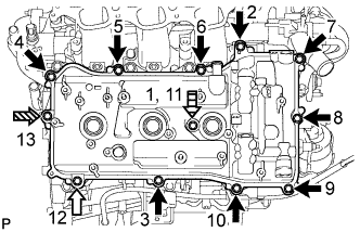
Temporarily install the cylinder head cover with the 12 bolts. Tighten the bolts uniformly in several steps.
- Torque:
- for bolt A and D
- 10 N*m { 102 kgf*cm, 7 ft.*lbf }
- for bolt B and C
- 21 N*m { 214 kgf*cm, 15 ft.*lbf }
Standard Bolt Item Length A 25 mm (0.984 in.) B 35 mm (1.38 in.) C 65 mm (2.56 in.) D 60 mm (2.36 in.) Text in Illustration Bolt A Bolt B 
Bolt C 
Bolt D Note
Do not start the engine for at least 2 hours after the installation.
-
-
INSTALL CYLINDER HEAD COVER SUB-ASSEMBLY LH
-
Remove any old packing (FIPG) material and be careful not to drop any oil on the contact surfaces of the cylinder head, timing chain cover or cylinder head cover.
-
Apply seal packing as shown in the illustration.
Seal packing Toyota Genuine Seal Packing Black, Three Bond 1207B or equivalent Standard seal diameter 2 to 3 mm (0.0787 to 0.118 in.) Text in Illustration Seal Packing Note
-
Remove any oil from the contact surface.
-
Install the cylinder head cover within 3 minutes and tighten the bolts within 15 minutes after applying seal packing.
-
-
Install 3 new gaskets as shown in the illustration.
-
Install a new gasket to the cylinder head cover.
-
Install the seal washers to the bolts.
-
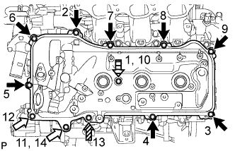
Temporarily install the cylinder head cover with the 12 bolts. Tighten the bolts uniformly in several steps.
- Torque:
- for bolt A and D
- 10 N*m { 102 kgf*cm, 7 ft.*lbf }
- for bolt B and C
- 21 N*m { 214 kgf*cm, 15 ft.*lbf }
Standard Bolt Item Length A 25 mm (0.984 in.) B 35 mm (1.38 in.) C 70 mm (2.76 in.) D 60 mm (2.36 in.) Text in Illustration Bolt A Bolt B Bolt C Bolt D Note
Do not start the engine for at least 2 hours after the installation.
-
-
INSTALL CRANKSHAFT PULLEY
-
Using SST, install the crankshaft pulley with the pulley set bolt.
- SST
- 09213-54015 ( 91651-60855 )
- 09330-00021
- Torque:
- 260 N*m { 2651 kgf*cm, 192 ft.*lbf }
-
-
INSTALL PCV VALVE SUB-ASSEMBLY
-
Apply adhesive to 2 or 3 threads of the PCV valve.
Adhesive Toyota Genuine Adhesive 1324, Three Bond 1324 or equivalent -
Install the PCV valve.
- Torque:
- 27 N*m { 275 kgf*cm, 20 ft.*lbf }
-
Install the PCV valve hose.
-
-
INSTALL SPARK PLUG
-
Install the 6 spark plugs.
- Torque:
- 18 N*m { 184 kgf*cm, 13 ft.*lbf }
-
-
INSTALL REAR WATER BY-PASS JOINT
-
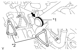
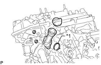
Text in Illustration *1 New O-Ring *2 New Gasket Apply soapy water to a new O-ring and install it to the water outlet pipe. Then install 2 new gaskets to the water ports LH and RH.
-
Install the rear water by-pass joint with the 2 bolts and 4 nuts.
- Torque:
- 10 N*m { 102 kgf*cm, 7 ft.*lbf }
-
-
INSTALL WATER INLET HOUSING
-
Install the 3 water by-pass hoses.
-
Apply soapy water to a new O-ring and install the O-ring to the water outlet pipe.
-
Install a new O-ring to the water outlet pipe.
-
Install a new gasket to the water pump.
-
Install the water inlet with the 5 bolts.
- Torque:
- 10 N*m { 102 kgf*cm, 7 ft.*lbf }
-
Connect the 3 water by-pass hoses.
-
-
INSTALL OIL FILTER BRACKET
-
Install the oil filter bracket and a new gasket with the 2 nuts and bolt.
- Torque:
- 21 N*m { 214 kgf*cm, 15 ft.*lbf }
-
-
INSTALL OIL FILTER ELEMENT
-
Clean the inside of the oil filter cap, the threads and O-ring groove.
-
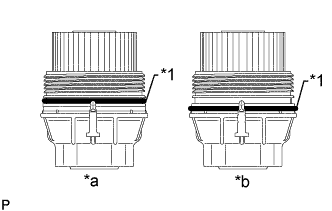
Text in Illustration *1 O-Ring *a CORRECT *b INCORRECT Apply a small amount of engine oil to a new O-ring and install the O-ring to the oil filter cap.
Note
-
Be sure to install the O-ring in the proper location, otherwise oil may leak.
-
Do not twist the O-ring.
-
-
Set a new oil filter element on the oil filter cap.
-
Remove any dirt or foreign matter from the installation surface of the engine.
-
Apply a small amount of engine oil to the O-ring again and temporarily install the oil filter cap.
Note
Do not pinch the O-ring for the cap.
-
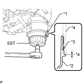
Text in Illustration *1 Oil Filter Bracket Clip *2 Oil Filler Cap *3 O-Ring *4 Oil Filter Bracket *a No Gap Using SST, tighten the oil filter cap.
- SST
- 09228-06501
- Torque:
- 25 N*m { 255 kgf*cm, 18 ft.*lbf }
Note
-
When tightening the oil filter cap, do not remove the oil filter bracket clip.
-
After tightening the oil filter cap, make sure that there is no gap and that the O-ring is not protruding.
-
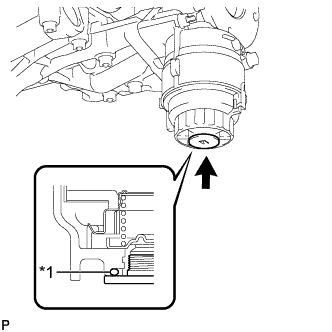
Text in Illustration *1 O-Ring Apply a small amount of engine oil to a new drain plug O-ring and install the O-ring to the oil filter cap.
Note
Before installing the O-ring, remove any dirt or foreign matter from the installation surface of the oil filter cap.
-
Install the oil filter drain plug.
- Torque:
- 13 N*m { 133 kgf*cm, 10 ft.*lbf }
Note
Make sure that the O-ring does not get caught between the parts.
-
-
INSTALL NO. 2 OIL PIPE
-
Make sure that there is no foreign matter on the mesh of the oil control valve filter RH.
Note
Do not touch the mesh when installing the oil control valve filter.
-
Install a new gasket and temporarily install the oil pipe (on the cylinder head side) with the oil check valve bolt.
-
Install the oil control valve filter RH to the oil pipe union. Install new gaskets and temporarily install the oil pipe (on the head cover side).
-
Tighten the oil pipe union (on the cylinder head side).
- Torque:
- 65 N*m { 663 kgf*cm, 48 ft.*lbf }
Note
If the link that connects the gaskets is broken, remove the connecting link by using side cutters or a similar tool.
-
Tighten the oil pipe union (on the head cover side).
- Torque:
- 65 N*m { 663 kgf*cm, 48 ft.*lbf }
-
-
INSTALL NO. 1 OIL PIPE
-
Make sure that there is no foreign matter on the mesh of the oil control valve filter LH.
Note
Do not touch the mesh when installing the oil control valve filter.
-
Install a new gasket and temporarily install the oil pipe (on the cylinder head side) with the oil check valve bolt.
-
Install the oil control valve filter LH to the oil pipe union. Install new gaskets and temporarily install the oil pipe (on the head cover side).
-
Tighten the oil pipe union (on the cylinder head side).
- Torque:
- 65 N*m { 663 kgf*cm, 48 ft.*lbf }
Note
If the link that connects the gaskets is broken, remove the connecting link by using side cutters or a similar tool.
-
Tighten the oil pipe union (on the head cover side).
- Torque:
- 65 N*m { 663 kgf*cm, 48 ft.*lbf }
-
-
INSTALL OIL FILLER CAP HOUSING
-
Text in Illustration *1 New Gasket Install a new gasket and the oil filler cap housing with the 2 nuts.
- Torque:
- 10 N*m { 102 kgf*cm, 7 ft.*lbf }
-
Install the oil filler cap.
-
-
INSTALL CAMSHAFT TIMING OIL CONTROL VALVE ASSEMBLY
-
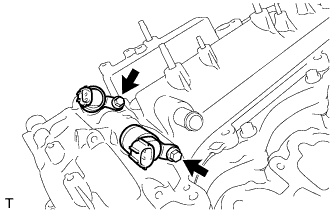
RH:
-
Apply a light coat of engine oil to 2 new O-rings.
-
Install the 2 O-rings to the 2 oil control valves.
-
Install the 2 oil control valves with the 2 bolts.
- Torque:
- 10 N*m { 102 kgf*cm, 7 ft.*lbf }
Note
Be careful that the O-ring is not cracked when installing the camshaft timing oil control valve.
-
-
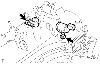
LH:
-
Apply a light coat of engine oil to 2 new O-rings.
-
Install the 2 O-rings to the 2 oil control valves.
-
Install the 2 oil control valves with the 2 bolts.
- Torque:
- 10 N*m { 102 kgf*cm, 7 ft.*lbf }
Note
Be careful that the O-ring is not cracked when installing the camshaft timing oil control valve.
-
-
-
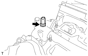
INSTALL CRANKSHAFT POSITION SENSOR
-
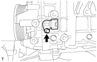
Install the sensor with the bolt.
- Torque:
- 10 N*m { 102 kgf*cm, 7 ft.*lbf }
-
-
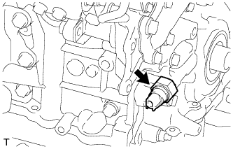
INSTALL VVT SENSOR
-
RH:
Install the 2 VVT sensors with the 2 bolts.
- Torque:
- 10 N*m { 102 kgf*cm, 7 ft.*lbf }
-
LH:
Install the 2 VVT sensors with the 2 bolts.
- Torque:
- 10 N*m { 102 kgf*cm, 7 ft.*lbf }
-
-
INSTALL CYLINDER BLOCK WATER DRAIN COCK SUB-ASSEMBLY
-
Apply adhesive to 2 or 3 threads of the water drain cock end.
Adhesive Toyota Genuine Adhesive 1324, Three Bond 1324 or equivalent -
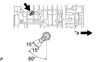
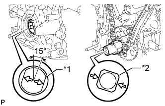
Text in Illustration *a Front Install the water drain cock.
- Torque:
- 30 N*m { 306 kgf*cm, 22 ft.*lbf }
Note
-
Install the water drain cock within 3 minutes after applying adhesive.
-
Do not expose the water drain cock to coolant within 1 hour of the installation.
-
Rotate the water drain cock clockwise to the position shown in the illustration.
Note
-
Do not rotate the water drain cock by more than 1 revolution (360°) after tightening the water drain cock to the specified torque.
-
Do not loosen the water drain cock after setting it correctly.
-
-
Install the water drain cock plug to the water drain cock.
- Torque:
- 13 N*m { 130 kgf*cm, 9 ft.*lbf }
-
-
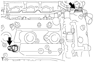
INSTALL ENGINE COOLANT TEMPERATURE SENSOR
-
Install a new gasket to the sensor.
-
Using a 19 mm deep socket wrench, install the sensor.
- Torque:
- 20 N*m { 200 kgf*cm, 14 ft.*lbf }
-
-
INSTALL ENGINE OIL PRESSURE SWITCH ASSEMBLY
-
Using a 24 mm deep socket wrench, install the oil pressure switch.
- Torque:
- 15 N*m { 153 kgf*cm, 11 ft.*lbf }
-