ENGINE ASSEMBLY REMOVAL

-
RECOVER REFRIGERANT FROM REFRIGERATION SYSTEM (w/ Air Conditioning System)
-
Start the engine.
-
Operate the cooler compressor under the conditions shown below:
Item Condition Engine Speed Idling Operating Time 3 minutes or more A/C Switch Status On Blower Switch Status HI Set Temperature MAX COOL This causes most of the compressor oil from the various components of the A/C system to collect in the A/C compressor.
Note
It is not necessary to operate the cooler compressor if the A/C does not operate because of compressor lock, etc.
-
Stop the engine.
-
Recover the refrigerant from the A/C system using a refrigerant recovery unit.
Tech Tips
Use the refrigerant recovery unit in accordance with the manufacturer's instruction manual.
-
-
DISCHARGE FUEL SYSTEM PRESSURE
-
Discharge the fuel system pressure Click here.
-
-
DISCONNECT CABLE FROM NEGATIVE BATTERY TERMINAL
Note
-
After turning the engine switch off, waiting time may be required before disconnecting the cable from the battery terminal. Therefore, make sure to read the disconnecting the cable from the battery terminal notice before proceeding with work Click here.
-
When disconnecting the cable, some systems need to be initialized after the cable is reconnected Click here.
-
-
REMOVE HOOD SUB-ASSEMBLY
-
Disconnect the washer nozzle hose.
-
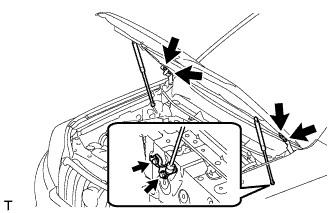
Remove the 8 bolts and hood.
Note
If the hood support is detached from the ball joint, it become non-reusable. Therefore, do not detach the hood support from the ball joint unless replacing it.
-
-
REMOVE COWL TOP VENTILATOR LOUVER SUB-ASSEMBLY
-
Remove the cowl top ventilator louver Click here.
-
-
REMOVE FRONT BUMPER COVER LOWER
-
Remove the clip, 5 bolts and front bumper cover lower.
-
-
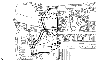
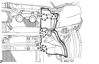
REMOVE NO. 1 ENGINE UNDER COVER SUB-ASSEMBLY
-
Remove the 4 bolts.
-
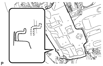
Unhook the engine under cover from the vehicle body as shown in the illustration.
-
-
REMOVE TRANSMISSION UNDER COVER
-
Remove the 2 bolts and transmission under cover.
-
-
REMOVE REAR ENGINE UNDER COVER ASSEMBLY
-
Remove the 4 bolts and rear engine under cover.
-
-
REMOVE FRONT FENDER APRON SEAL LH
-
Remove the 5 clips and front fender apron seal.
-
-
REMOVE FRONT FENDER APRON SEAL RH
-
Remove the 5 clips and front fender apron seal.
-
-
REMOVE FRONT NO. 1 FENDER APRON TO FRAME SEAL LH
-
Remove the 5 clips and front No. 1 fender apron to frame seal.
-
-
REMOVE FRONT NO. 1 FENDER APRON TO FRAME SEAL RH
-
Remove the 5 clips and front No. 1 fender apron to frame seal.
-
-
REMOVE UPPER RADIATOR SUPPORT SEAL
-
Remove the 13 clips and upper radiator support seal.
-
-
DRAIN ENGINE OIL
-
Remove the oil filler cap.
-
Remove the oil pan drain plug and drain the engine oil into a container.
-
Install a new gasket and the oil pan drain plug.
- Torque:
- 40 N*m { 408 kgf*cm, 30 ft.*lbf }
-
-
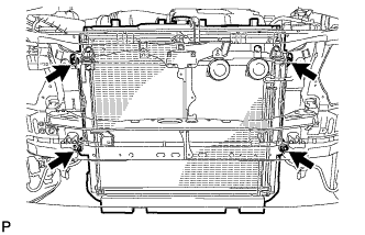
DRAIN ENGINE COOLANT
CAUTION:
Do not remove the radiator cap while the engine and radiator are still hot. Pressurized, hot engine coolant and steam may be released and cause serious burns.
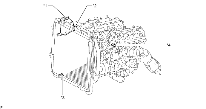
Text in Illustration *1 Reservoir Cap *2 Radiator Cap *3 Radiator Drain Cock Plug *4 Cylinder Block Drain Cock Plug
-
Loosen the radiator drain cock plug.
-
Remove the radiator cap and drain the coolant.
Tech Tips
Collect the coolant in a container and dispose of it according to the regulations in your area.
-
Loosen the cylinder block drain cock plug and drain the coolant from the engine.
-
-
DISCONNECT CABLE FROM POSITIVE BATTERY TERMINAL
-
REMOVE BATTERY HOLD DOWN CLAMP
-
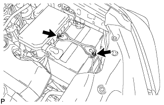
Loosen the 2 nuts and remove the battery hold down clamp.
-
-
REMOVE BATTERY
-
REMOVE BATTERY TRAY
-
REMOVE V-BANK COVER
-
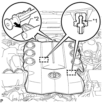
Text in Illustration *1 Pin *2 Hook Raise the front of the V-bank cover to detach the 2 pins. Then remove the 2 V-bank cover hooks from the bracket, and remove the V-bank cover.
-
-
REMOVE FRONT BUMPER COVER
-
Remove the front bumper cover Click here.
-
-
REMOVE AIR CLEANER CAP AND HOSE
-
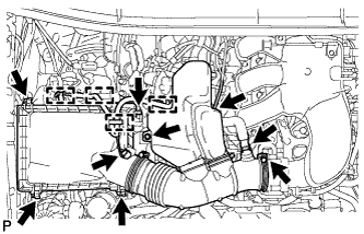
Remove the air cleaner cap and hose.
-
Disconnect the mass air flow meter connector, vacuum hose and ventilation hose and detach the 4 clamps.
-
Loosen the clamp.
-
Unfasten the 4 hook clamps, and then remove the bolt and air cleaner cap and hose.
-
-
-
REMOVE AIR CLEANER CASE SUB-ASSEMBLY
-
Remove the air cleaner filter element.
-
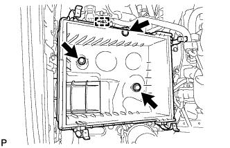
Detach the wire harness clamp.
-
Remove the 3 bolts and air cleaner case.
-
-
REMOVE UPPER FRONT BUMPER RETAINER
-
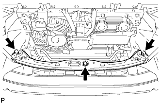
Remove the 3 bolts and retainer.
-
-
REMOVE RADIATOR SIDE DEFLECTOR RH
-
Using a clip remover, detach the 3 claws and remove the clip. Then move the side deflector so that the radiator can be removed in the step below.
-
-
REMOVE RADIATOR SIDE DEFLECTOR LH
-
Using a clip remover, detach the 3 claws and remove the clip. Then move the side deflector so that the radiator can be removed in the step below.
-
-
REMOVE NO. 1 RADIATOR HOSE
-
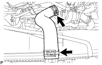
REMOVE NO. 2 RADIATOR HOSE
-
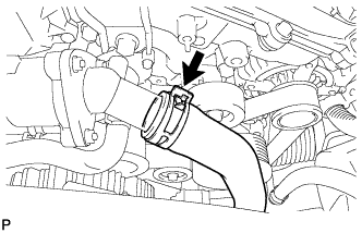
Disconnect the radiator hose from the water inlet.
-
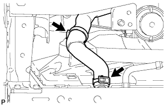
Detach the clamp and remove the radiator hose.
-
-
REMOVE RADIATOR RESERVOIR
-
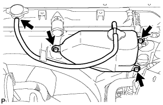
Disconnect the reservoir hose from the upper side of the radiator tank.
-
Remove the 3 bolts and radiator reservoir.
-
-
DISCONNECT OIL COOLER TUBE (w/ Warmer)
-
Detach the claw to open the flexible hose clamp, and then remove the 2 bolts to disconnect the oil cooler tube from the fan shroud.
-
-
DISCONNECT OIL COOLER TUBE (w/ Air Cooled Transmission Oil Cooler)
-
Detach the claw to open the flexible hose clamp, and then remove the 2 bolts to disconnect the oil cooler tube from the fan shroud.
-
-
REMOVE FAN SHROUD
-
Loosen the 4 nuts holding the fluid coupling fan.
-
Remove the fan and generator V-belt Click here.
-
Remove the 2 bolts holding the fan shroud.
-
Remove the 4 nuts of the fluid coupling fan, and then remove the shroud together with the coupling fan.
Note
Be careful not to damage the radiator core.
-
Remove the fan pulley from the water pump.
-
-
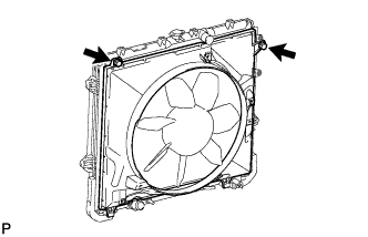
REMOVE RADIATOR ASSEMBLY
-
Text in Illustration *A w/ Warmer *B w/ Air Cooled Transmission Oil Cooler for Automatic Transmission:
Disconnect the 2 oil cooler hoses.
-
Remove the 4 bolts and radiator.
-
-
REMOVE AIR TUBE ASSEMBLY (w/ Secondary Air Injection System)
-
for Bank 1 Side:
Remove the bolt and disconnect the air tube assembly from the emission control valve set.
-
for Bank 2 Side:
Remove the 2 bolts and disconnect the air tube assembly from the No. 2 emission control valve set.
-
-
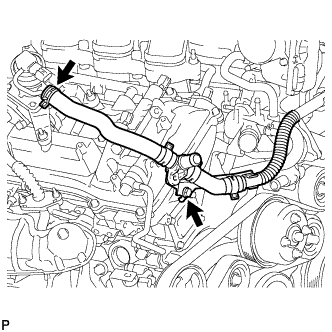
REMOVE INTAKE AIR SURGE TANK
-
Disconnect the throttle body connector.
-
Disconnect the No. 4 water by-pass hose.
-
Disconnect the No. 5 water by-pass hose.
-
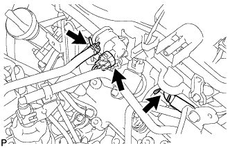
Disconnect the No. 1 fuel vapor feed hose.
-
Disconnect the No. 1 vacuum switching valve connector.
-
Disconnect the No. 1 ventilation hose.
-
Detach the 2 heater hose clamps.
-
Remove the 2 bolts and throttle body bracket.
-
Using a clip remover, detach the wire harness clamp.
-
Remove the 2 bolts and No. 1 surge tank stay.
-
Remove the 2 bolts and No. 2 surge tank stay.
-

Remove the 2 nuts, 4 bolts and intake air surge tank.
-
Remove the gasket.
-
-
REMOVE FAN AND GENERATOR V BELT
-
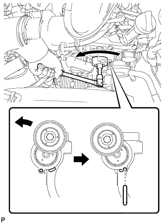
While turning the belt tensioner counterclockwise, align the service hole for the belt tensioner and the belt tensioner fixing position, and then insert a bar of φ 6 mm (0.236 in.) into the service hole to fix the belt tensioner in place.
Tech Tips
The pulley bolt for the belt tensioner has a left-hand thread.
-
Remove the V belt.
-
-
DISCONNECT VANE PUMP ASSEMBLY
-
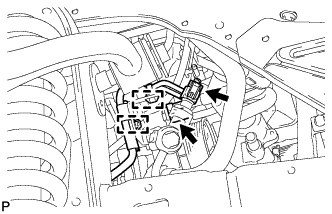
Disconnect the 2 connectors.
-
Detach the 2 wire harness clamps.
-
Remove the 2 bolts and disconnect the vane pump.
-
-
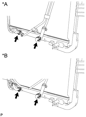
DISCONNECT DISCHARGE HOSE SUB-ASSEMBLY (w/ Air Conditioning System)
-
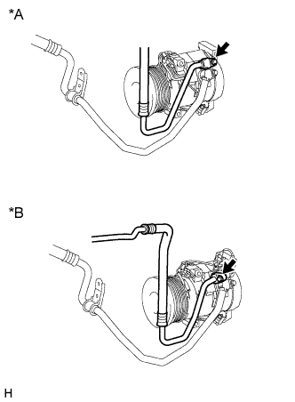
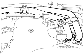
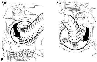
Text in Illustration *A except Model Code GRJ150L-GKFEKV, GRJ150L-GKAEKV *B Model Code GRJ150L-GKFEKV, GRJ150L-GKAEKV Remove the bolt and disconnect the discharge hose from the cooler compressor.
-
Remove the O-ring from the discharge hose.
Note
Seal the openings of the disconnected parts using vinyl tape to prevent moisture and foreign matter from entering them.
-
-
DISCONNECT SUCTION HOSE SUB-ASSEMBLY (w/ Air Conditioning System)
-
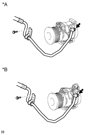
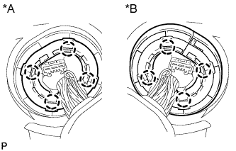
Text in Illustration *A except Model Code GRJ150L-GKFEKV, GRJ150L-GKAEKV *B Model Code GRJ150L-GKFEKV, GRJ150L-GKAEKV Remove the 2 bolts and disconnect the suction hose from the cooler compressor.
-
Remove the O-ring from the suction hose.
Note
Seal the openings of the disconnected parts using vinyl tape to prevent moisture and foreign matter from entering them.
-
-
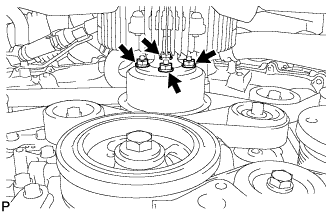
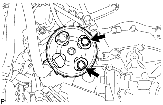
REMOVE COOLER COMPRESSOR ASSEMBLY (w/ Air Conditioning System)
-
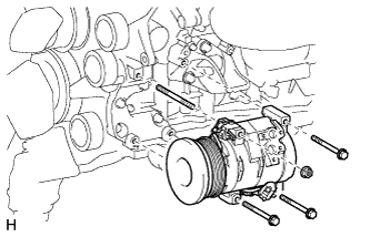
Disconnect the connector.
-
Remove the 3 bolts, nut and the cooler compressor.
-
Remove the stud bolt.
-
-
REMOVE IDLER PULLEY ASSEMBLY (w/o Air Conditioning System)
-
Remove the 3 bolts and idler pulley.
-
-
REMOVE FRONT EXHAUST PIPE ASSEMBLY
-
Remove the front exhaust pipe Click here.
-
-
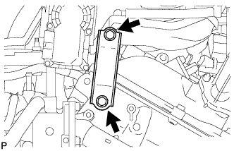
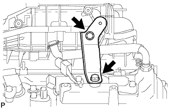
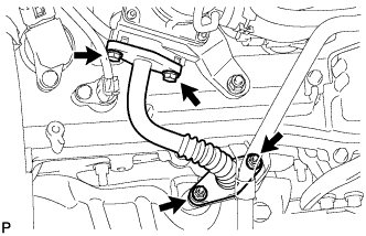
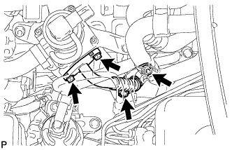
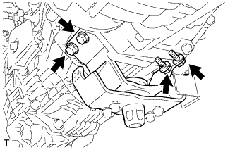
REMOVE MANIFOLD STAY
-
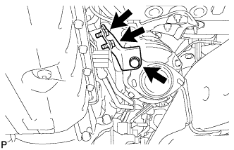
Remove the 3 bolts and manifold stay.
-
-
REMOVE AIR TUBE (w/ Secondary Air Injection System)
-
Remove the 2 bolts, 2 nuts and air tube.
-
Remove the 2 gaskets from the air tube.
Note
Be careful not to damage the installation surface of the gaskets.
-
-
DISCONNECT NO. 2 STEERING INTERMEDIATE SHAFT SUB-ASSEMBLY (for RHD)
-
for Manual tilt and manual telescopic steering column:
Disconnect the No. 2 steering intermediate shaft Click here.
-
for Power tilt and power telescopic steering column:
Disconnect the No. 2 steering intermediate shaft Click here.
-
-
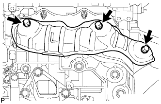
REMOVE NO. 1 EXHAUST MANIFOLD HEAT INSULATOR
-
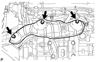
Remove the 3 bolts and heat insulator.
-
-
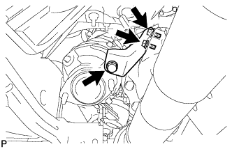
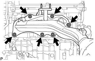
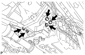
REMOVE EXHAUST MANIFOLD SUB-ASSEMBLY RH
-

w/ Secondary Air Injection System:
-
Disconnect the air fuel ratio sensor connector.
-
Remove the 6 nuts, manifold and gasket.
-
-
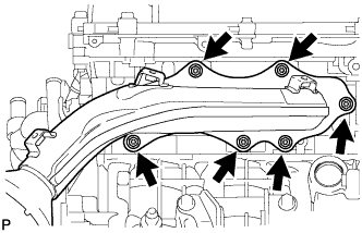
w/o Secondary Air Injection System:
-
Disconnect the air fuel ratio sensor connector.
-
Remove the 6 nuts, manifold and gasket.
-
-
-
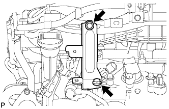
REMOVE NO. 2 MANIFOLD STAY
-
Remove the 3 bolts and No. 2 manifold stay.
-
-
REMOVE NO. 2 AIR TUBE (w/ Secondary Air Injection System)
-
Remove the 2 bolts, 2 nuts and No. 2 air tube.
-
Remove the 2 gaskets from the No. 2 air tube.
Note
Be careful not to damage the installation surface of the gaskets.
-
-
REMOVE NO. 2 EXHAUST MANIFOLD HEAT INSULATOR
-
Remove the 3 bolts and heat insulator.
-
-
REMOVE EXHAUST MANIFOLD SUB-ASSEMBLY LH
-
w/ Secondary Air Injection System:
-
Disconnect the air fuel ratio sensor connector.
-
Remove the 6 nuts, manifold and gasket.
-
-
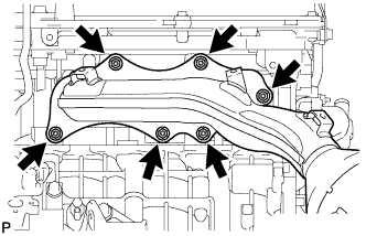
w/o Secondary Air Injection System:
-
Disconnect the air fuel ratio sensor connector.
-
Remove the 6 nuts, manifold and gasket.
-
-
-
REMOVE WIRING HARNESS CLAMP BRACKET
-
Detach the clamp.
-
Remove the bolt and wiring harness clamp bracket.
-
-
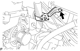
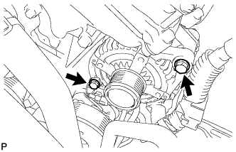
REMOVE GENERATOR ASSEMBLY
-
Open the terminal cap.
-
Remove the nut and disconnect the wire harness from terminal B.
-
Disconnect the generator connector from the generator assembly.
-
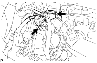
Remove the 2 bolts and disconnect the wire harness.
-
Disconnect the wire harness clamp.
-
Remove the bolt and disconnect the generator bracket.
-
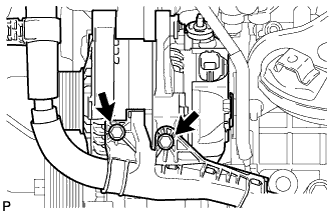
Remove the 2 bolts and generator assembly.
-
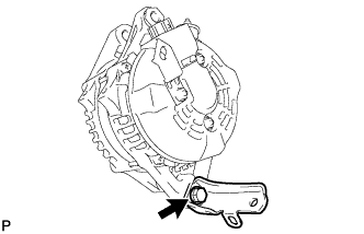
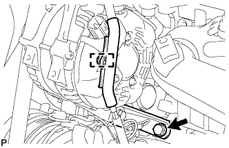
Remove the bolt and generator bracket.
-
-
REMOVE STARTER ASSEMBLY
-
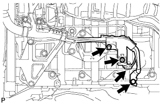
Remove the bolt and disconnect the ground wire.
-
Disconnect the starter connector.
-
Open the terminal cap.
-
Remove the nut and bolt, and then disconnect the starter wire.
-
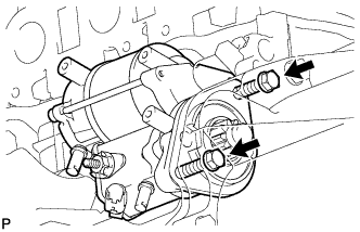
Remove the 2 bolts and starter assembly.
-
-
REMOVE DRIVE PLATE AND TORQUE CONVERTER CLUTCH SETTING BOLT (for Automatic Transmission)
-
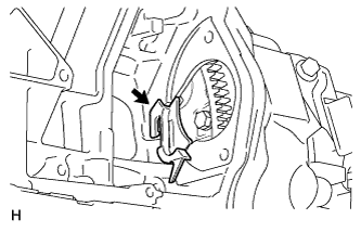
Remove the flywheel housing side cover.
-
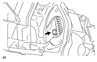
Turn the crankshaft to gain access to the 6 bolts and remove each bolt while holding the crankshaft pulley setting bolt with a wrench.
-
-
DISCONNECT ENGINE WIRE
-
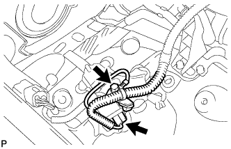
Remove the bolt and disconnect the connector.
-
Remove the glove compartment door Click here.
-
Disconnect the ECM connector.
-
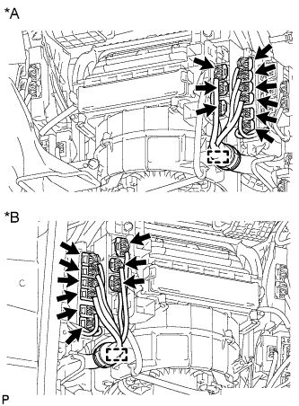
Text in Illustration *A for LHD *B for RHD Detach the clamp and disconnect the 9 connectors.
-
Text in Illustration *A for LHD *B for RHD Detach the grommet from the wire harness support.
-
Text in Illustration *A for LHD *B for RHD Detach the 4 claws to remove the wire harness support from the vehicle, and then pull out the ECM connector to remove it from the vehicle.
-
-
-
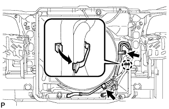
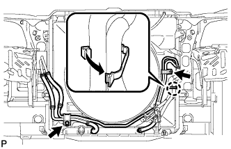
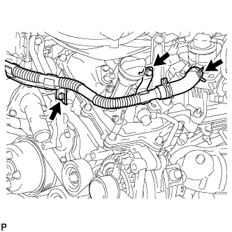
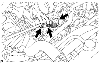
DISCONNECT HEATER WATER HOSE ASSEMBLY
-
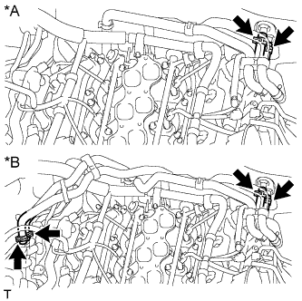
Text in Illustration *A w/o Rear Heater *B w/ Rear Heater w/o Rear heater:
Disconnect the 2 hoses and heater water hose.
-
w/ Rear heater:
Disconnect the 4 hoses and heater water hose.
-
-
DISCONNECT NO. 1 AND NO. 2 FUEL PIPES
-
Remove the No. 2 fuel pipe clamp from the fuel tube connector.
-
Disconnect the No. 1 and No. 2 fuel pipes Click here.
-
-
REMOVE FRONT PROPELLER SHAFT ASSEMBLY
-
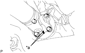
Text in Illustration *a Matchmark Place matchmarks on the propeller shaft flange and differential.
-
Remove the 4 nuts, 4 bolts, 4 washers and front propeller shaft assembly.
-
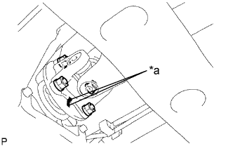
Text in Illustration *a Matchmark Place matchmarks on the propeller shaft flange and transfer flange.
-
Remove the 4 nuts, 4 washers and front propeller shaft assembly.
-
-
REMOVE PROPELLER SHAFT ASSEMBLY
-
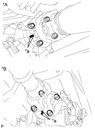
Text in Illustration *A for 3 Door *B for 5 Door *a Matchmark Place matchmarks on the propeller shaft flange and transfer flange.
-
Remove the 4 nuts and 4 washers.
-
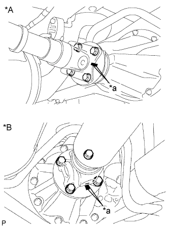
Text in Illustration *A for 3 Door *B for 5 Door *a Matchmark Place matchmarks on the propeller shaft flange and differential flange.
-
Remove the 4 nuts, 4 bolts and 4 washers.
-
Remove the propeller shaft.
-
-
REMOVE MANUAL TRANSMISSION ASSEMBLY (for Manual Transmission)
-
Remove the manual transmission from the vehicle Click here.
-
-
REMOVE AUTOMATIC TRANSMISSION ASSEMBLY (for Automatic Transmission)
-
Remove the automatic transmission from the vehicle Click here.
-
-
REMOVE REAR NO. 1 ENGINE MOUNTING INSULATOR (for Automatic Transmission)
-
Remove the bolt and rear engine mounting heat insulator.
-
Remove the 4 bolts and rear engine mounting insulator from the transmission.
-
-
REMOVE REAR NO. 1 ENGINE MOUNTING INSULATOR (for Manual Transmission)
-
Remove the 4 bolts and engine mounting insulator from the manual transmission.
-
-
DISCONNECT SUCTION HOSE SUB-ASSEMBLY (for Automatic Transmission)
-
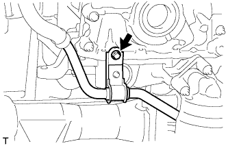
Remove the bolt and disconnect the suction hose.
-
-
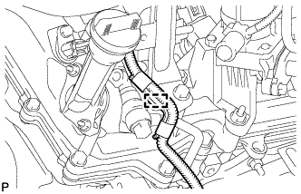
DISCONNECT OIL COOLER TUBE SUB-ASSEMBLY (for Automatic Transmission)
-
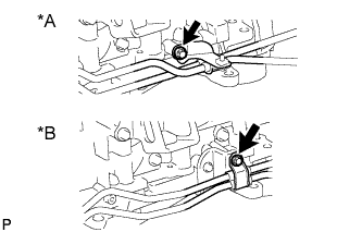
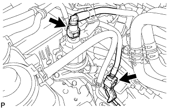
Text in Illustration *A w/o Air Cooled Transmission Oil Cooler *B w/ Air Cooled Transmission Oil Cooler Remove the bolt and disconnect the oil cooler tube.
-
-
REMOVE CLUTCH COVER ASSEMBLY (for Manual Transmission)
-
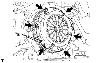
Text in Illustration *a Matchmark Put matchmarks on the clutch cover and flywheel.
-
Loosen each set bolt one turn at a time until spring tension is released.
-
Remove the 6 set bolts and pull off the clutch cover.
Note
Do not drop the clutch disc.
-
-
REMOVE CLUTCH DISC ASSEMBLY (for Manual Transmission)
Note
Keep the lining part of the clutch disc, the pressure plate and the surface of the flywheel away from oil and foreign matter.
-
REMOVE FLYWHEEL SUB-ASSEMBLY (for Manual Transmission)
-
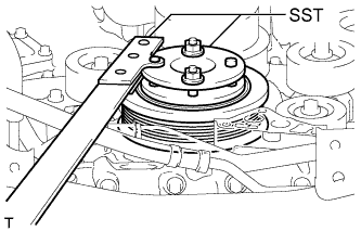
Using SST, hold the crankshaft.
- SST
- 09213-54015 ( 91651-60855 )
- 09330-00021
-
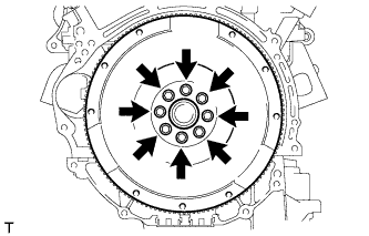
Remove the 8 bolts and flywheel.
Note
Do not reuse the bolts.
-
-
REMOVE DRIVE PLATE AND RING GEAR SUB-ASSEMBLY (for Automatic Transmission)
-
Using SST, hold the crankshaft.
- SST
- 09213-54015 ( 91651-60855 )
- 09330-00021
-
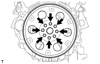
Remove the 8 bolts, rear spacer, drive plate and front spacer.
-
-
REMOVE ENGINE ASSEMBLY
-
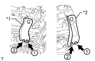
Text in Illustration *1 No. 1 Engine Hanger *2 No. 2 Engine Hanger Install 2 engine hangers with 4 bolts as shown in the illustration.
- Torque:
- 33 N*m { 337 kgf*cm, 24 ft.*lbf }
Tech Tips
No. 1 Engine Hanger 12281-31110 No. 2 Engine Hanger 12282-31140 Bolt 91671-C0830 -
Attach an engine sling device and hang the engine with a chain block.
-
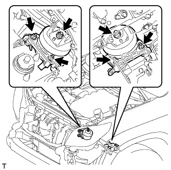
Remove the 6 nuts from the front engine mounting insulator LH and RH.
-
Lift the engine out of the vehicle carefully.
Note
Make sure the engine is clear of all wiring and hoses.
-
Remove the front engine mounting insulator LH and RH.
-
Place the engine onto a work bench.
-
-
INSTALL ENGINE STAND
-
Install the engine onto an engine stand with bolts.
-