CYLINDER HEAD GASKET INSTALLATION

-
INSPECT CYLINDER HEAD SET BOLT
-
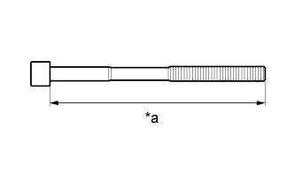
Using a vernier caliper, measure the length of the cylinder head set bolt from the seat to the end.
Text in Illustration *a Measurement Length Standard length 141.3 to 142.7 mm (5.56 to 5.62 in.) Maximum length 143.7 mm (5.66 in.) If the length is more than the maximum, replace the cylinder head set bolt.
-
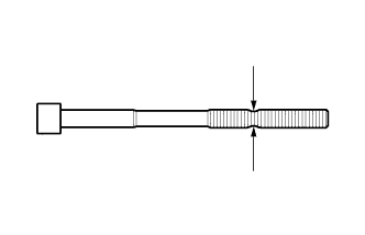
Using a vernier caliper, measure the diameter of the elongated thread at the narrowest visible area.
Standard diameter 10.73 to 10.97 mm (0.422 to 0.432 in.) Minimum diameter 10.40 mm (0.409 in.) If the diameter is less than the minimum, replace the cylinder head set bolt.
Tech Tips
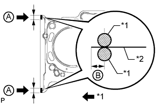
If a visual check reveals no excessively thin areas, check the center of the bolt (refer to illustration) and find the area that has the smallest diameter.
-
-
INSPECT CYLINDER HEAD SUB-ASSEMBLY
-
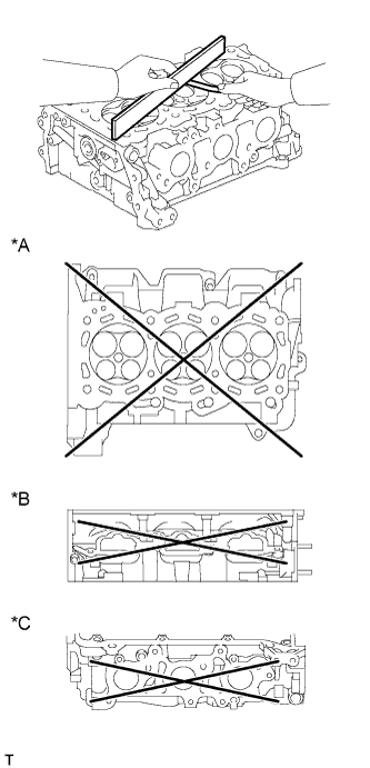
Text in Illustration *A Cylinder Block Side *B Intake Side *C Exhaust Side Using a precision straightedge and feeler gauge, measure the warpage of the surfaces which contact the cylinder block sub-assembly and manifolds.
Standard Warpage Item Specified Condition Cylinder block side 0.05 mm (0.00197 in.) Intake side 0.08 mm (0.00315 in.) Exhaust side 0.08 mm (0.00315 in.) Maximum Warpage Item Specified Condition Cylinder block side 0.10 mm (0.00394 in.) Intake side 0.10 mm (0.00394 in.) Exhaust side 0.10 mm (0.00394 in.) If the warpage is more than the maximum, replace the cylinder head sub-assembly.
-
Using a dye penetrant, check the intake ports, exhaust ports and cylinder surface for cracks.
If cracked, replace the cylinder head sub-assembly.
-
-
INSTALL CYLINDER HEAD GASKET
-
Remove any old packing (FIPG) material and be careful not to drop any oil on the contact surfaces of the cylinder head or cylinder block.
-
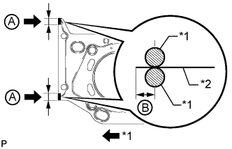
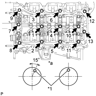
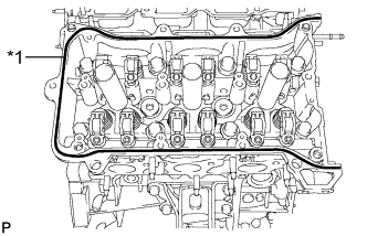
Text in Illustration *1 Seal Packing *2 Gasket Apply seal packing to a new cylinder head gasket as shown in the illustration.
Seal packing Toyota Genuine Seal Packing Black, Three Bond 1207B or equivalent Standard seal diameter 2.5 to 3.0 mm (0.0984 to 0.118 in.) Seal Packing Application Range A 10 to 15 mm (0.394 to 0.591 in.) B 1.25 to 1.5 mm (0.0492 to 0.0591 in.) Note
-
Remove any oil from the contact surface.
-
Install the cylinder head gasket within 3 minutes and tighten the bolts within 15 minutes after applying seal packing.
-
Do not add engine oil within 2 hours of installation.
-
-
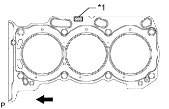
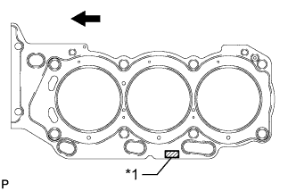
Text in Illustration *1 Lot No. 
Engine Front Place the cylinder head gasket on the cylinder block surface with the front face of the Lot No. stamp upward.
Note
Make sure that the gasket is installed facing the proper direction.
-
-
INSTALL CYLINDER HEAD SUB-ASSEMBLY
-
Place the cylinder head on the cylinder block.
Note
-
Gently place the cylinder head in order not to damage the gasket with the bottom part of the head.
-
Make sure that no oil is on the mounting surface of the cylinder head.
Tech Tips
The cylinder head bolts are tightened in 3 progressive steps.
-
-
Apply a light coat of engine oil to the threads and under the heads of the cylinder head bolts.
-
Step 1:
-
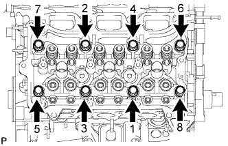
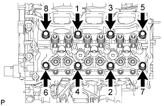
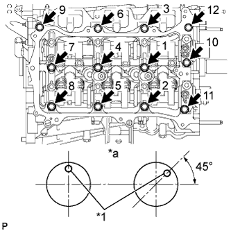
Using a 10 mm bi-hexagon wrench, install and uniformly tighten the 8 cylinder head bolts with the plate washers in several steps in the sequence shown in the illustration.
- Torque:
- 36 N*m { 367 kgf*cm, 27 ft.*lbf }
-
-
Step 2:
-
Mark the front side of each cylinder head bolt head with paint.
-
Tighten the cylinder head bolts another 90°.
-
-
Step 3:
-
Tighten the cylinder head bolts an additional 90°.
-
Check that the paint mark is now at a 180° angle to the front.
Note
Thoroughly wipe clean any seal packing.
-
-
-
INSTALL NO. 2 CYLINDER HEAD GASKET
-
Remove any old packing (FIPG) material and be careful not to drop any oil on the contact surfaces of the cylinder head or cylinder block.
-
Text in Illustration *1 Seal Packing *2 Gasket Apply seal packing to a new cylinder head gasket as shown in the illustration.
Seal packing Toyota Genuine Seal Packing Black, Three Bond 1207B or equivalent Standard seal diameter 2.5 to 3.0 mm (0.0984 to 0.118 in.) Seal Packing Application Range A 10 to 15 mm (0.394 to 0.591 in.) B 1.25 to 1.5 mm (0.0492 to 0.0591 in.) Note
-
Remove any oil from the contact surface.
-
Install the cylinder head gasket within 3 minutes and tighten the bolts within 15 minutes after applying seal packing.
-
Do not add engine oil within 2 hours of installation.
-
-
Text in Illustration *1 Lot No. Engine Front Place the cylinder head gasket on the cylinder block surface with the front face of the Lot No. stamp upward.
Note
Make sure that the gasket is installed facing the proper direction.
-
-
INSTALL CYLINDER HEAD LH
-
Place the cylinder head on the cylinder block.
Note
-
Gently place the cylinder head in order not to damage the gasket with the bottom part of the head.
-
Make sure that no oil is on the mounting surface of the cylinder head.
Tech Tips
The cylinder head bolts are tightened in 3 progressive steps.
-
-
Apply a light coat of engine oil to the threads and under the heads of the cylinder head bolts.
-
Step 1:
-
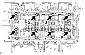
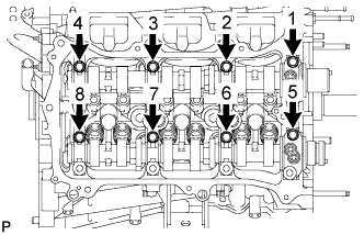
Using a 10 mm bi-hexagon wrench, install and uniformly tighten the 8 cylinder head bolts with the plate washers in several steps in the sequence shown in the illustration.
- Torque:
- 36 N*m { 367 kgf*cm, 27 ft.*lbf }
-
-
Step 2:
-
Mark the front side of each cylinder head bolt head with paint.
-
Tighten the cylinder head bolts another 90°.
-
-
Step 3:
-
Tighten the cylinder head bolts an additional 90°.
-
Check that the paint mark is now at a 180° angle to the front.
-
-
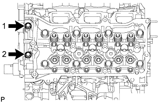
Tighten the 2 bolts in the order shown in the illustration.
- Torque:
- 30 N*m { 306 kgf*cm, 22 ft.*lbf }
Note
Thoroughly wipe clean any seal packing.
-
-
INSTALL REAR WATER BY-PASS JOINT
-
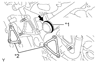
Text in Illustration *1 New O-Ring *2 New Gasket Apply soapy water to a new O-ring and install it to the water outlet pipe. Then install 2 new gaskets to the water ports LH and RH.
-
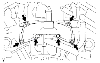
Install the rear water by-pass joint with the 2 bolts and 4 nuts.
- Torque:
- 10 N*m { 102 kgf*cm, 7 ft.*lbf }
-
-
INSTALL VALVE STEM CAP
-
Apply a light coat of engine oil to the valve stem caps.
-
Install the 24 valve stem caps to the cylinder head.
-
-
INSTALL VALVE LASH ADJUSTER ASSEMBLY
-
Inspect the valve lash adjuster Click here.
-
Install the 24 valve lash adjusters to the cylinder head.
Note
Install the lash adjuster at the same place it was removed from.
-
-
INSTALL NO. 1 VALVE ROCKER ARM SUB-ASSEMBLY
-
Apply engine oil to the lash adjuster tips and valve stem cap ends.
-
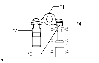
Text in Illustration *1 Valve Rocker Arm *2 Lash Adjuster *3 Valve Stem *4 Valve Stem Cap Install the 24 valve rocker arms as shown in the illustration.
-
-
INSTALL CAMSHAFT BEARING CAP (for Bank 2)
-
Apply a light coat of engine oil to the camshaft journals, camshaft housings and bearing caps.
-
Install the No. 3 camshaft and No. 4 camshaft to the camshaft housing.
-
Check the marks and numbers on the camshaft bearing caps and place each of them in the proper position facing the proper direction.
-
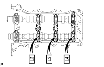
Temporarily install the 8 bolts in the order shown in the illustration.
- Torque:
- 10 N*m { 102 kgf*cm, 7 ft.*lbf }
-
-
INSTALL CAMSHAFT HOUSING SUB-ASSEMBLY LH
-
Text in Illustration *1 Valve Rocker Arm *2 Lash Adjuster *3 Valve Stem *4 Valve Stem Cap Make sure that the valve rocker arm is installed as shown in the illustration.
-
Text in Illustration *1 Seal Packing Apply seal packing in a continuous line as shown in the illustration.
Seal packing Toyota Genuine Seal Packing Black, Three Bond 1207B or equivalent Seal diameter 3.5 to 4.5 mm (0.138 to 0.177 in.) Note
-
Remove any oil from the contact surface.
-
Install the camshaft housing within 3 minutes and tighten the bolts within 15 minutes after applying seal packing.
-
-
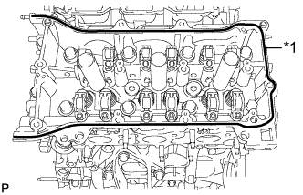
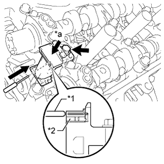
Text in Illustration *1 Knock Pin *a Front View Install the camshaft housing sub-assembly LH and tighten the 13 bolts in the order shown in the illustration.
- Torque:
- 28 N*m { 286 kgf*cm, 21 ft.*lbf }
Note
-
When installing the camshaft housing sub-assembly LH, it is necessary to correctly position the camshafts as shown in the illustration. Failure to correctly position these parts may result in damage due to contact between the pistons and valves. If a camshaft is rotated with a piston at TDC, valve contact will occur.
-
If any of the bolts are loosened during installation, remove the camshaft housing sub-assembly LH, clean the installation surfaces and reapply seal packing.
-
If the camshaft housing sub-assembly LH is removed because any of the bolts are loosened during installation, make sure that the previously applied seal packing does not enter any oil passages.
-
Do not start the engine for at least 2 hours after installing.
-
Tighten the 8 bolts in the order shown in the illustration.
- Torque:
- 16 N*m { 163 kgf*cm, 12 ft.*lbf }
Note
Thoroughly wipe clean any seal packing.
-
-
INSTALL CAMSHAFT BEARING CAP (for Bank 1)
-
Apply a light coat of engine oil to the camshaft journals, camshaft housings and bearing caps.
-
Install the camshaft and No. 2 camshaft to the camshaft housing.
-
Check the marks and numbers on the camshaft bearing caps and place each of them in the proper position facing the proper direction.
-
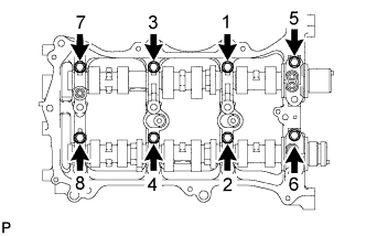
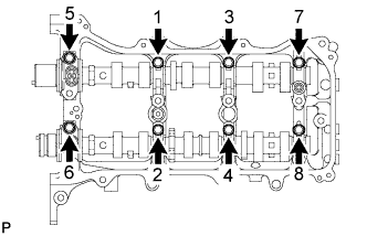
Temporarily install the 8 bearing cap bolts in the order shown in the illustration.
- Torque:
- 10 N*m { 102 kgf*cm, 7 ft.*lbf }
-
-
INSTALL CAMSHAFT HOUSING SUB-ASSEMBLY RH
-
Text in Illustration *1 Valve Rocker Arm *2 Lash Adjuster *3 Valve Stem *4 Valve Stem Cap Make sure that the No. 1 valve rocker arm sub-assembly is installed as shown in the illustration.
-
Text in Illustration *1 Seal Packing Apply seal packing in a continuous line as shown in the illustration.
Seal packing Toyota Genuine Seal Packing Black, Three Bond 1207B or equivalent Seal diameter 3.5 to 4.5 mm (0.138 to 0.177 in.) Note
-
Remove any oil from the contact surface.
-
Install the camshaft housing within 3 minutes and tighten the bolts within 15 minutes after applying seal packing.
-
-
Text in Illustration *1 Knock Pin *a Front View Install the camshaft housing sub-assembly RH and tighten the 12 bolts in the order shown in the illustration.
- Torque:
- 28 N*m { 286 kgf*cm, 21 ft.*lbf }
Note
-
When installing the camshaft housing RH, it is necessary to correctly position the camshafts as shown in the illustration.
Failure to correctly position these parts may result in damage due to contact between the pistons and valves. If a camshaft is rotated with a piston at TDC, valve contact will occur.
-
If any of the bolts are loosened during installation, remove the camshaft housing sub-assembly RH, clean the installation surfaces and reapply seal packing.
-
If the camshaft housing sub-assembly RH is removed because any of the bolts are loosened during installation, make sure that the previously applied seal packing does not enter any oil passages.
-
Do not start the engine for at least 2 hours after installing.
-
Tighten the 8 bolts in the order shown in the illustration.
- Torque:
- 16 N*m { 163 kgf*cm, 12 ft.*lbf }
Note
Thoroughly wipe clean any seal packing.
-
-
INSTALL NO. 3 CHAIN TENSIONER ASSEMBLY
-
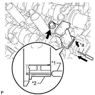
Text in Illustration *1 Pin *2 Plunger *a Push Install the No. 3 chain tensioner assembly with the bolt.
- Torque:
- 21 N*m { 214 kgf*cm, 15 ft.*lbf }
-
Push in the tensioner and insert a pin with a diameter of 1.0 mm (0.0394 in.) into the hole to hold the tensioner.
-
-
INSTALL CAMSHAFT TIMING GEARS AND NO. 2 CHAIN (for Bank 2)
-
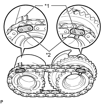
Text in Illustration *1 Timing Mark *2 Mark Plate Align the mark plates (yellow) with the timing marks of the camshaft timing gear assemblies as shown in the illustration.
-
Apply a light coat of engine oil to the bolt threads and bolt-seating surface.
-
Align the knock pin of the camshaft with the pin hole of the camshaft timing gear assembly. Install the camshaft timing gear assembly and camshaft timing exhaust gear LH with the No. 2 chain sub-assembly installed.
-
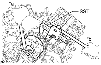
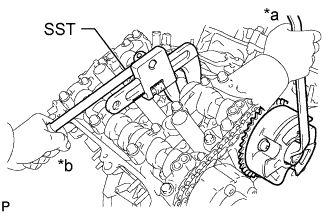
Text in Illustration *a Turn *b Hold Using SST to hold the hexagonal portion of each camshaft, tighten the bolts of the camshaft timing gear assembly and camshaft timing exhaust gear assembly.
- SST
- 09922-10010
- Torque:
- 100 N*m { 1020 kgf*cm, 74 ft.*lbf }
-
Remove the pin from the No. 3 chain tensioner assembly.
-
-
INSTALL NO. 2 CHAIN TENSIONER ASSEMBLY
-
Text in Illustration *1 Pin *2 Plunger *a Push Install the No. 2 chain tensioner assembly with the bolt.
- Torque:
- 21 N*m { 214 kgf*cm, 15 ft.*lbf }
-
Push in the No. 2 chain tensioner assembly and insert a pin with a diameter of 1.0 mm (0.0394 in.) into the hole to hold the tensioner.
-
-
INSTALL CAMSHAFT TIMING GEARS AND NO. 2 CHAIN (for Bank 1)
-
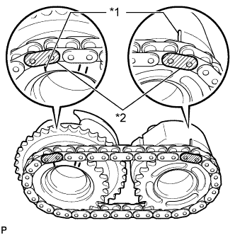
Text in Illustration *1 Timing Mark *2 Mark Plate Align the mark plates (yellow) with the timing marks of the camshaft timing gear assemblies as shown in the illustration.
-
Apply a light coat of engine oil to the bolt threads and bolt-seating surface.
-
Align the knock pin of the camshaft with the pin hole of the camshaft timing gear assembly. Install the camshaft timing gear assembly and camshaft timing exhaust gear assembly with the No. 2 chain sub-assembly installed.
-
Text in Illustration *a Turn *b Hold Using SST to hold the hexagonal portion of each camshaft, tighten the bolts of the camshaft timing gear assembly and camshaft timing exhaust gear assembly.
- SST
- 09922-10010
- Torque:
- 100 N*m { 1020 kgf*cm, 74 ft.*lbf }
-
Remove the pin from the No. 2 chain tensioner assembly.
-
-
INSTALL NO. 1 CHAIN VIBRATION DAMPER
-
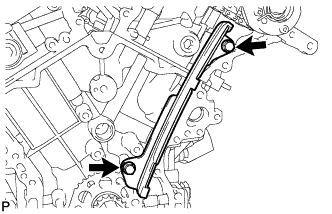
Install the No. 1 chain vibration damper with the 2 bolts.
- Torque:
- 23 N*m { 229 kgf*cm, 17 ft.*lbf }
-
-
INSTALL NO. 2 CHAIN VIBRATION DAMPER
-
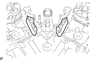
Install the 2 No. 2 chain vibration dampers.
-
-
INSTALL CRANKSHAFT TIMING SPROCKET
-
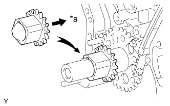
Text in Illustration *a Inward Align the key groove of the timing sprocket with the timing sprocket set key.
-
Install the timing sprocket to the crankshaft with the sprocket facing inward as shown in the illustration.
-
-
INSTALL NO. 1 IDLE GEAR SHAFT
-
Apply a light coat of engine oil to the sliding surface of the No. 1 idle gear shaft.
-
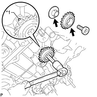
Text in Illustration *1 Knock Pin Temporarily install the No. 1 idle gear shaft and No. 1 idle gear with the No. 2 idle gear shaft while aligning the knock pin of the No. 1 idle gear shaft with the knock pin groove of the cylinder block.
Note
Make sure that the idle gear is installed facing the proper direction.
-
Using a 10 mm hexagon wrench, tighten the No. 2 idle gear shaft.
- Torque:
- 60 N*m { 612 kgf*cm, 44 ft.*lbf }
-
Remove the bar from the chain tensioner.
-
-
INSTALL CHAIN SUB-ASSEMBLY
-
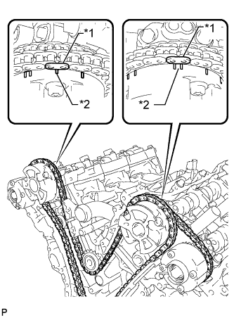
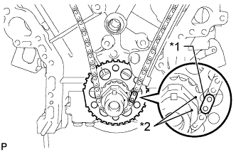
Text in Illustration *1 Mark Plate *2 Timing Mark Align the mark plate and timing marks as shown in the illustration and install the chain.
Tech Tips
The camshaft mark plates are orange.
-
Do not pass the chain around the crankshaft, just temporarily place it on the crankshaft.
-
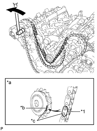
Text in Illustration *1 Chain Plate *a When idle sprocket is reused *b Mark *c Align 
Turn Turn the camshaft timing gear assembly on bank 1 counterclockwise to tighten the chain between the banks.
Note
When the idle sprocket assembly is reused, align the chain plate with the mark where the plate had been when tightening the chain between the banks.
-
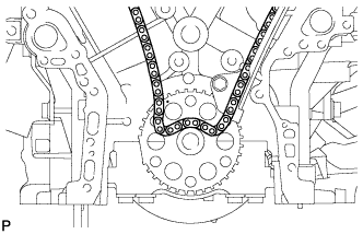
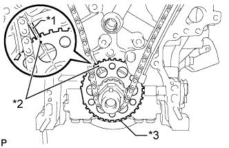
Text in Illustration *1 Mark Plate *2 Timing Mark Align the mark plate and timing marks as shown in the illustration and install the chain to the crankshaft timing sprocket.
Tech Tips
The crankshaft mark plate is yellow.
-
Temporarily install the pulley set bolt.
-
Text in Illustration *1 Center Line *2 Timing Mark *3 Sensor Plate Turn the crankshaft clockwise to set it to the RH block bore center line (TDC/compression).
-
-
INSTALL CHAIN TENSIONER SLIPPER
-
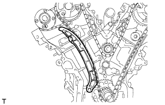
Install the chain tensioner slipper.
-
-
INSTALL NO. 1 CHAIN TENSIONER ASSEMBLY
-
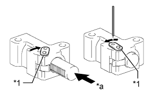
Text in Illustration *1 Stopper Plate *a Push Turn the stopper plate of the tensioner clockwise and push in the plunger of the tensioner as shown in the illustration.
-
Turn the stopper plate of the tensioner counterclockwise and insert a pin of φ1.27 mm (0.0500 in.) into the holes on the stopper plate and tensioner to fix the stopper plate in place.
-

Install the chain tensioner with the 2 bolts.
- Torque:
- 10 N*m { 102 kgf*cm, 7 ft.*lbf }
-
Remove the pin from the No. 1 chain tensioner.
-
-
INSPECT VALVE TIMING
-
Check the camshaft timing marks.
Note
-
Check each timing mark from a viewpoint directly in line with the center of the camshaft and the timing mark on each camshaft timing gear.
-
If the timing marks are checked from any other viewpoint, the valve timing may appear misaligned.
-
-
Check that each camshaft timing mark is positioned as shown in the illustration.
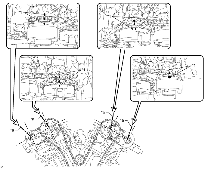
Text in Illustration *1 Timing Mark - - *a Viewpoint - - Tech Tips
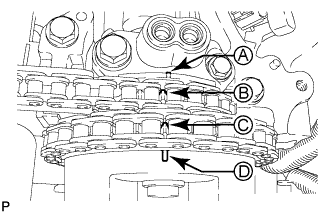
for Intake Camshaft:
Be sure to check mark A at the point when marks B, C and D are positioned in line. If the marks are checked from any other viewpoint, they cannot be checked correctly.
-
If the valve timing is misaligned, reinstall the timing chain.
-
Remove the pulley set bolt.
-
-
INSTALL TIMING CHAIN COVER SUB-ASSEMBLY
-
Install the timing chain cover Click here.
-