CAMSHAFT REMOVAL

-
DISCONNECT CABLE FROM NEGATIVE BATTERY TERMINAL
Note
-
After turning the engine switch off, waiting time may be required before disconnecting the cable from the battery terminal. Therefore, make sure to read the disconnecting the cable from the battery terminal notice before proceeding with work Click here.
-
When disconnecting the cable, some systems need to be initialized after the cable is reconnected Click here.
-
-
REMOVE FRONT BUMPER COVER LOWER
-
Remove the clip, 5 bolts and front bumper cover lower.
-
-
REMOVE NO. 1 ENGINE UNDER COVER SUB-ASSEMBLY
-
Remove the 4 bolts.
-
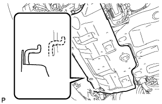
Unhook the engine under cover from the vehicle body as shown in the illustration.
-
-
DRAIN ENGINE OIL
-
Remove the oil filler cap.
-
Remove the oil pan drain plug and drain the engine oil into a container.
-
Install a new gasket and the oil pan drain plug.
- Torque:
- 40 N*m { 408 kgf*cm, 30 ft.*lbf }
-
-
DRAIN ENGINE COOLANT
CAUTION:
Do not remove the radiator cap while the engine and radiator are still hot. Pressurized, hot engine coolant and steam may be released and cause serious burns.
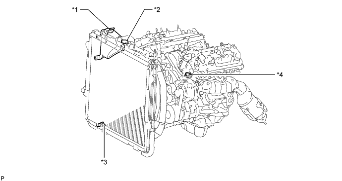
Text in Illustration *1 Reservoir Cap *2 Radiator Cap *3 Radiator Drain Cock Plug *4 Cylinder Block Drain Cock Plug
-
Loosen the radiator drain cock plug.
-
Remove the radiator cap and drain the coolant.
Tech Tips
Collect the coolant in a container and dispose of it according to the regulations in your area.
-
Loosen the cylinder block drain cock plug and drain the coolant from the engine.
-
-
REMOVE UPPER RADIATOR SUPPORT SEAL
-
Remove the 13 clips and upper radiator support seal.
-
-
DISCONNECT CABLE FROM POSITIVE BATTERY TERMINAL
-
REMOVE BATTERY HOLD DOWN CLAMP
-
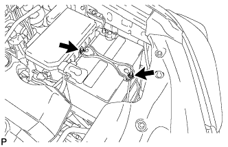
Loosen the 2 nuts and remove the battery hold down clamp.
-
-
REMOVE BATTERY
-
REMOVE BATTERY TRAY
-
REMOVE V-BANK COVER
-
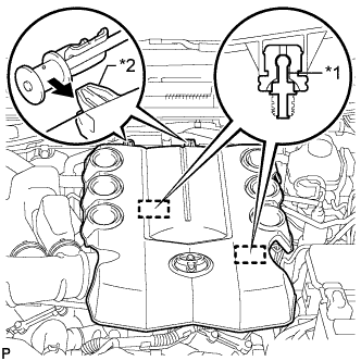
Text in Illustration *1 Pin *2 Hook Raise the front of the V-bank cover to detach the 2 pins. Then remove the 2 V-bank cover hooks from the bracket, and remove the V-bank cover.
-
-
REMOVE AIR CLEANER CAP AND HOSE
-
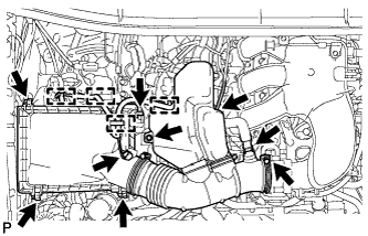
Remove the air cleaner cap and hose.
-
Disconnect the mass air flow meter connector, vacuum hose and ventilation hose and detach the 4 clamps.
-
Loosen the clamp.
-
Unfasten the 4 hook clamps, and then remove the bolt and air cleaner cap and hose.
-
-
-
REMOVE AIR CLEANER CASE SUB-ASSEMBLY
-
Remove the air cleaner filter element.
-
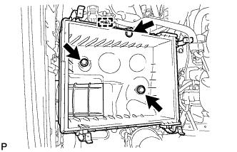
Detach the wire harness clamp.
-
Remove the 3 bolts and air cleaner case.
-
-
REMOVE NO. 1 RADIATOR HOSE
-
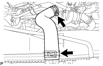
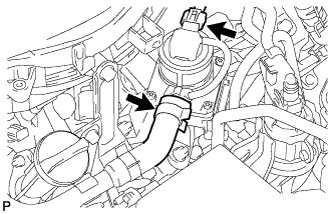
REMOVE NO. 2 RADIATOR HOSE
-
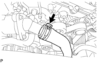
Disconnect the radiator hose from the water inlet.
-
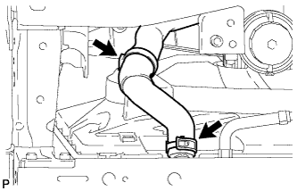
Detach the clamp and remove the radiator hose.
-
-
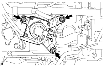
REMOVE RADIATOR RESERVOIR
-
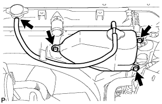
Disconnect the reservoir hose from the upper side of the radiator tank.
-
Remove the 3 bolts and radiator reservoir.
-
-
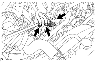
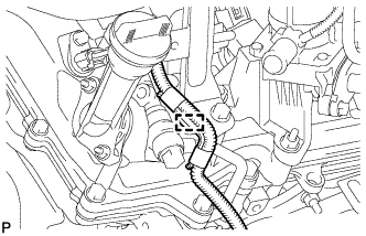
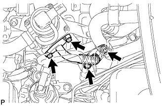
DISCONNECT OIL COOLER TUBE (w/ Warmer)
-
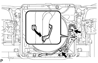
Detach the claw to open the flexible hose clamp, and then remove the 2 bolts to disconnect the oil cooler tube from the fan shroud.
-
-
DISCONNECT OIL COOLER TUBE (w/ Air Cooled Transmission Oil Cooler)
-
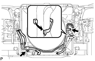
Detach the claw to open the flexible hose clamp, and then remove the 2 bolts to disconnect the oil cooler tube from the fan shroud.
-
-
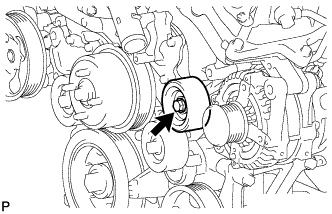
REMOVE FAN SHROUD
-
Loosen the 4 nuts holding the fluid coupling fan.
-
Remove the fan and generator V-belt Click here.
-
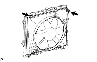
Remove the 2 bolts holding the fan shroud.
-
Remove the 4 nuts of the fluid coupling fan, and then remove the shroud together with the coupling fan.
Note
Be careful not to damage the radiator core.
-
Remove the fan pulley from the water pump.
-
-
REMOVE AIR TUBE ASSEMBLY (w/ Secondary Air Injection System)
-
for Bank 1 Side:
Remove the bolt and disconnect the air tube assembly from the emission control valve set.
-
for Bank 2 Side:
Remove the 2 bolts and disconnect the air tube assembly from the No. 2 emission control valve set.
-
-
REMOVE INTAKE AIR SURGE TANK
-
Disconnect the throttle body connector.
-
Disconnect the No. 4 water by-pass hose.
-
Disconnect the No. 5 water by-pass hose.
-
Disconnect the No. 1 fuel vapor feed hose.
-
Disconnect the No. 1 vacuum switching valve connector.
-
Disconnect the No. 1 ventilation hose.
-
Detach the 2 heater hose clamps.
-
Remove the 2 bolts and throttle body bracket.
-
Using a clip remover, detach the wire harness clamp.
-
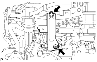
Remove the 2 bolts and No. 1 surge tank stay.
-
Remove the 2 bolts and No. 2 surge tank stay.
-

Remove the 2 nuts, 4 bolts and intake air surge tank.
-
Remove the gasket.
-
-
REMOVE AIR TUBE (w/ Secondary Air Injection System)
-
Remove the 2 bolts, 2 nuts and air tube.
-
Remove the 2 gaskets from the air tube.
Note
Be careful not to damage the installation surface of the gaskets.
-
-
REMOVE NO. 2 AIR TUBE (w/ Secondary Air Injection System)
-
Remove the 2 bolts, 2 nuts and No. 2 air tube.
-
Remove the 2 gaskets from the No. 2 air tube.
Note
Be careful not to damage the installation surface of the gaskets.
-
-
REMOVE EMISSION CONTROL VALVE SET (w/ Secondary Air Injection System)
-
Disconnect the emission control valve set connector.
-
Disconnect the No. 1 air hose from the emission control valve set.
-
Remove the 3 nuts and emission control valve set.
-
-
REMOVE NO. 2 EMISSION CONTROL VALVE SET (w/ Secondary Air Injection System)
-
Disconnect the No. 2 emission control valve set connector.
-
Disconnect the No. 3 air hose.
-
Remove the 3 nuts and No. 2 emission control valve set.
-
-
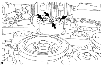
REMOVE IGNITION COIL ASSEMBLY
-
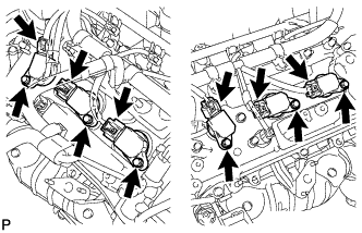
Disconnect the 6 ignition coil connectors.
-
Remove the 6 bolts and 6 ignition coils.
-
-
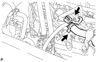
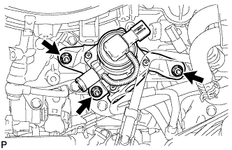
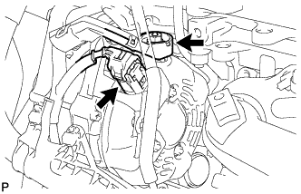
DISCONNECT VANE PUMP ASSEMBLY
-
Disconnect the 2 connectors.
-
Detach the 2 wire harness clamps.
-
Remove the 2 bolts and disconnect the vane pump.
-
-
REMOVE NO. 2 IDLER PULLEY SUB-ASSEMBLY
-
for Integrated Type:
Remove the bolt and No. 2 idler pulley.
-
for Separate Type:
Remove the bolt, No. 2 idler pulley cover plate, No. 2 idler pulley and idler pulley cover plate.
-
-
REMOVE WIRING HARNESS CLAMP BRACKET
-
Detach the clamp.
-
Remove the bolt and wiring harness clamp bracket.
-
-
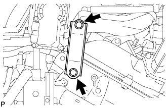
REMOVE NO. 2 EXHAUST MANIFOLD HEAT INSULATOR
-
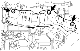
Remove the 3 bolts and heat insulator.
-
-
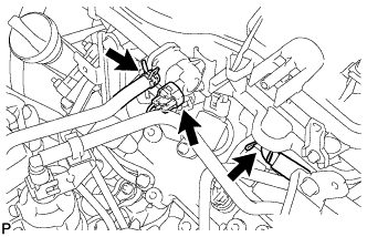
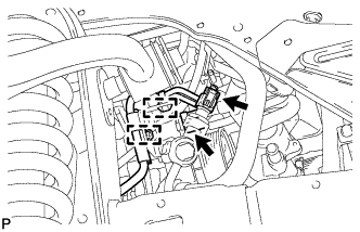
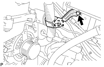
REMOVE GENERATOR ASSEMBLY
-
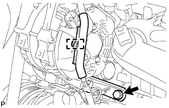
Open the terminal cap.
-
Remove the nut and disconnect the wire harness from terminal B.
-
Disconnect the generator connector from the generator assembly.
-
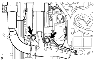
Remove the 2 bolts and disconnect the wire harness.
-
Disconnect the wire harness clamp.
-
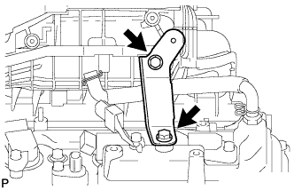
Remove the bolt and disconnect the generator bracket.
-
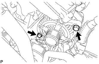
Remove the 2 bolts and generator assembly.
-
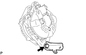
Remove the bolt and generator bracket.
-
-
REMOVE ENGINE OIL LEVEL DIPSTICK GUIDE
-
Remove the dipstick.
-
Remove the bolt and dipstick guide.
-
Remove the O-ring from the dipstick guide.
-
-
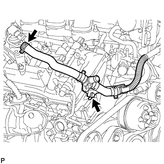
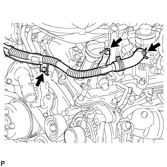
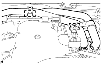
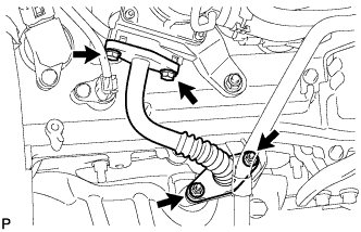
REMOVE WATER BY-PASS PIPE SUB-ASSEMBLY (w/ Oil Cooler)
-
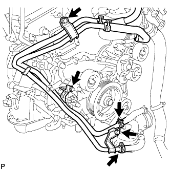
Disconnect the 2 hoses.
-
Remove the 3 bolts and water by-pass pipe.
-
-
REMOVE NO. 1 OIL PIPE
-
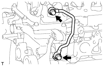
Remove the 2 oil pipe unions, oil control valve filter LH, 3 gaskets and No. 1 oil pipe.
Note
Do not touch the mesh when removing the oil control valve filter.
-
-
REMOVE NO. 2 OIL PIPE
-
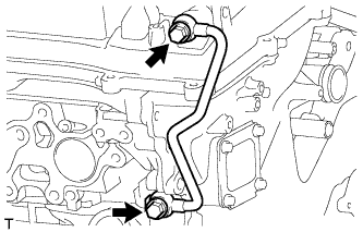
Remove the 2 oil pipe unions, oil control valve filter RH, 3 gaskets and No. 2 oil pipe.
Note
Do not touch the mesh when removing the oil control valve filter.
-
-
REMOVE REAR CYLINDER HEAD COVER
-
Remove the 3 bolts and cover.
-
-
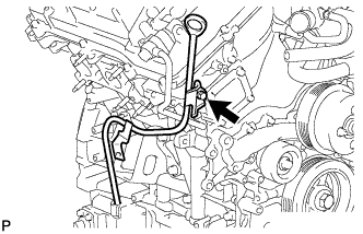
DISCONNECT FUEL PIPE SUB-ASSEMBLY
-
Remove the 2 bolts and disconnect the fuel pipe.
-
-
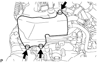
REMOVE CYLINDER HEAD COVER SUB-ASSEMBLY LH
-
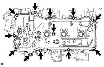
Remove the 12 bolts, seal washer, cylinder head cover and gasket.
Tech Tips
Make sure the removed parts are returned to the same places they were removed from.
-
Remove the 3 gaskets.
-
-
REMOVE CYLINDER HEAD COVER SUB-ASSEMBLY
-
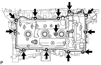
Remove the 12 bolts, seal washer, cylinder head cover and gasket.
Tech Tips
Make sure the removed parts are returned to the same places they were removed from.
-
Remove the 3 gaskets.
-
-
REMOVE TIMING CHAIN COVER PLATE
-
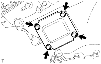
Remove the 4 bolts, timing chain cover plate and gasket.
-
-
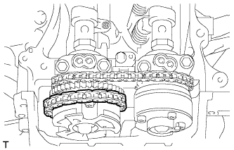
SET NO. 1 CYLINDER TO TDC/COMPRESSION
-
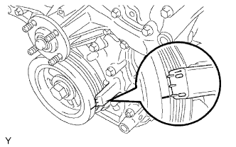
Turn the crankshaft pulley and align the notch with the "0" timing mark of the timing chain cover.
-
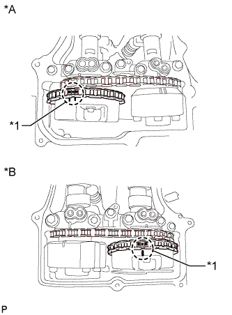
Text in Illustration *A for Bank 2 *B for Bank 1 *1 Paint Mark Check that the timing marks of the camshaft timing gears are aligned with the timing marks of the bearing caps as shown in the illustration.
Tech Tips
If the marks are not aligned, turn the crankshaft again to align the marks.
-
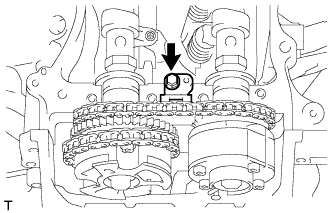
Place paint marks on the timing marks and sprockets of each camshaft timing gear and on the links of the No. 1 chain.
Tech Tips
Be sure to place the paint marks on 2 links of the chain and on the sprockets of the camshaft timing gears at the locations of the timing marks of the camshaft timing gears.
-
-
REMOVE NO. 1 CHAIN TENSIONER ASSEMBLY
-
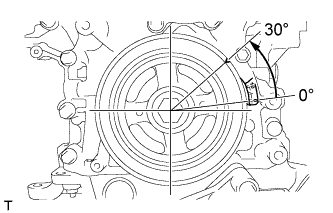
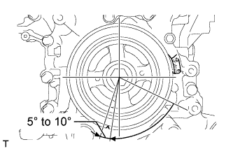
Turn the crankshaft approximately 30° counterclockwise so that there is some slack in the chain.
Tech Tips
This prevents the valves and pistons from interfering with each other.
-
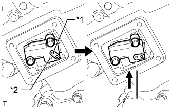
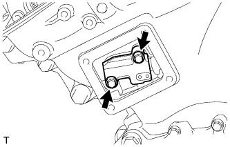
Text in Illustration *1 Lever Hole *2 Tensioner Hole Align the hole in the lever of the tensioner with the hole in the tensioner body as shown in the illustration, and then insert a pin with a diameter of 1.27 mm (0.0500 in.) into the hole.
-
Turn the crankshaft clockwise and align the notch with the "0" timing mark of the timing chain cover.
-
Remove the 2 bolts and chain tensioner.
Note
Do not drop the No. 1 chain tensioner assembly or bolts into the timing chain cover.
-
-
DISCONNECT CHAIN SUB-ASSEMBLY (for Bank 1)
-
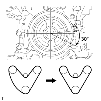
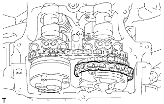
Turn the crankshaft clockwise until it is in the position shown in the illustration so that there is some slack in the chain between the banks.
Tech Tips
When turning the crankshaft, engine oil may spray out of the oil holes.
CAUTION:
As the camshafts turn suddenly, do not touch the camshafts or camshaft timing gears.
-
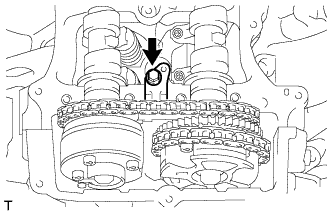
Turn the crankshaft clockwise until it is in the position shown in the illustration so that the chain can be removed easily.
Tech Tips
When turning the crankshaft, engine oil may spray out of the oil holes.
-
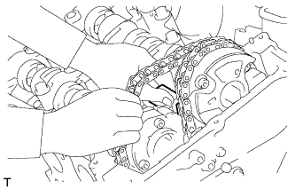
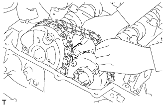
Remove the chain from the sprocket of the camshaft timing gear and set it on the gear.
CAUTION:
As the camshaft may turn suddenly and pinch your fingers when the chain is removed, pinch the chain and lift it upward to remove it from the sprocket.
-
-
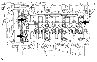
REMOVE CAMSHAFT BEARING CAP (for Bank 1)
-
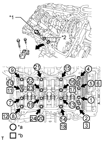
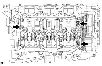
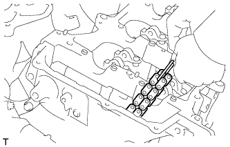
Text in Illustration *1 Bolt *2 Washer *a Part Removal *b Installation of Bolts and Washers for Temporary Installation of camshaft housing Remove the bolts and bearing caps in the order shown in the illustration. Immediately after removing a bearing cap, install bolts and washers for temporary installation of the camshaft housing in the order shown in the illustration.
- Torque:
- 10 N*m { 102 kgf*cm, 7 ft.*lbf }
Tech Tips
-
Arrange the removed parts so that they can be reinstalled in their original locations.
-
Part number of bolt for temporary installation of camshaft housing: 91551-G0845 (quantity: 8)
-
Part number of washer for temporary installation of camshaft housing: 90201-12028 (quantity: 16)
Note
-
Do not install the bearing caps when installing bolts and washers for temporary installation of the camshaft housing.
-
Be sure to follow the numerical order when performing this procedure.
-
Do not allow bolts and washers for temporary installation of the camshaft housing to contact the camshaft.
-
Do not drop bolts and washers for temporary installation of the camshaft housing into the cylinder head.
-
-
REMOVE NO. 2 CAMSHAFT
-
Remove the bolt of the No. 2 chain tensioner assembly.
-
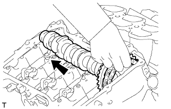
Remove the No. 2 chain tensioner assembly while lifting up the No. 2 camshaft.
-
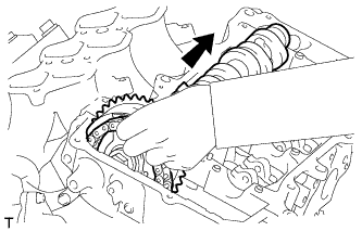
While lifting up the No. 2 camshaft, pass it through the No. 2 chain and pull it out towards the front of the vehicle to remove it.
-
-
REMOVE CAMSHAFT
-
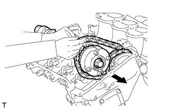
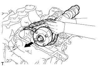
Lift up the rear of the camshaft so that it is at an angle.
-
Remove the chain from the camshaft timing gear and pull out the camshaft and No. 2 chain towards the rear of the vehicle to remove them.
Note
Do not drop the chain into the gap between the engine and cover.
-
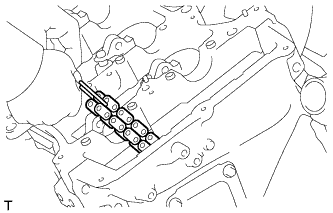
Suspend the chain with a string or equivalent.
-
-
DISCONNECT CHAIN SUB-ASSEMBLY (for Bank 2)
-
Turn the crankshaft counterclockwise and align the notch with the "0" timing mark of the timing chain cover.
-
Remove the chain from the sprocket of the camshaft timing gear and set it on the gear.
CAUTION:
As the camshaft may turn suddenly and pinch your fingers when the chain is removed, pinch the chain and lift it upward to remove it from the sprocket.
-
-
REMOVE CAMSHAFT BEARING CAP (for Bank 2)
-
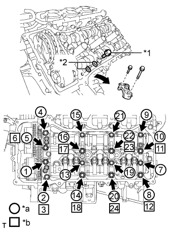
Text in Illustration *1 Bolt *2 Washer *a Part Removal *b Installation of Bolts and Washers for Temporary Installation of camshaft housing Remove the bolts and bearing caps in the order shown in the illustration. Immediately after removing a bearing cap, install bolts and washers for temporary installation of the camshaft housing in the order shown in the illustration.
- Torque:
- 10 N*m { 102 kgf*cm, 7 ft.*lbf }
Tech Tips
-
Arrange the removed parts so that they can be reinstalled in their original locations.
-
Part number of bolt for temporary installation of camshaft housing: 91551-G0845 (quantity: 8)
-
Part number of washer for temporary installation of camshaft housing: 90201-12028 (quantity: 16)
Note
-
Do not install the bearing caps when installing bolts and washers for temporary installation of the camshaft housing.
-
Be sure to follow the numerical order when performing this procedure.
-
Do not allow bolts and washers for temporary installation of the camshaft housing to contact the camshaft.
-
Do not drop bolts and washers for temporary installation of the camshaft housing into the cylinder head.
-
-
REMOVE NO. 4 CAMSHAFT
-
Remove the bolt of the No. 3 chain tensioner assembly.
-
Remove the No. 3 chain tensioner assembly while lifting up the No. 4 camshaft.
-
While lifting up the No. 4 camshaft, pass it through the No. 2 chain and pull it out towards the front of the vehicle to remove it.
-
-
REMOVE NO. 3 CAMSHAFT
-
Lift up the rear of the camshaft so that it is at an angle.
-
Remove the chain from the camshaft timing gear and pull out the No. 3 camshaft and No. 2 chain towards the rear of the vehicle to remove them.
Note
Do not drop the chain into the gap between the engine and cover.
-
Suspend the chain with a string or equivalent.
-
-
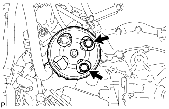
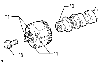
REMOVE CAMSHAFT TIMING GEAR ASSEMBLY
-
Fix the camshaft in place.
Note
Be careful not to damage the camshaft.
-
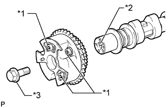
Text in Illustration *1 Do not remove *2 Straight Pin *3 Flange Bolt Remove the flange bolt and camshaft timing gear assembly.
Note
-
Do not remove the other 3 bolts.
-
If planning to reuse the camshaft timing gear, be sure to release the straight pin lock before installing the camshaft timing gear.
-
-
-
REMOVE CAMSHAFT TIMING EXHAUST GEAR ASSEMBLY
-
Fix the camshaft in place.
Note
Be careful not to damage the camshaft.
-
Text in Illustration *1 Do not remove *2 Straight Pin *3 Flange Bolt Remove the flange bolt and camshaft timing exhaust gear assembly.
Note
-
Be sure not to remove the other 4 bolts.
-
If planning to reuse the gear, be sure to release the straight pin lock before installing the gear.
-
-