SFI SYSTEM, Diagnostic DTC:P0412

| DTC Code | DTC Name |
|---|---|
| P0412 | Secondary Air Injection System Switching Valve "A" Circuit |
DESCRIPTION
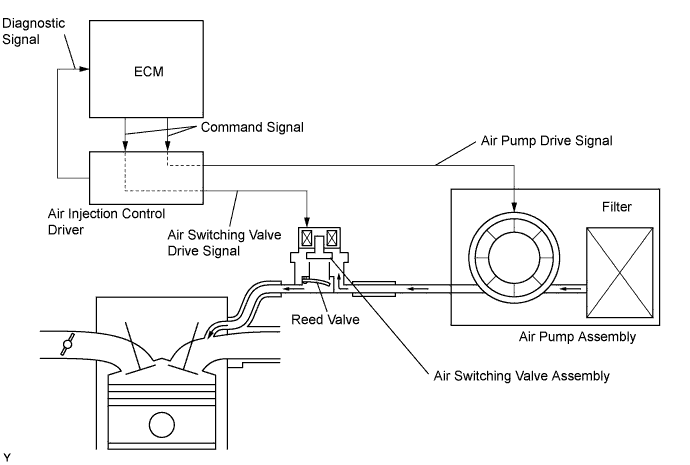
The Secondary Air Injection (AIR) system consists of an air pump, the air switching valve, a pressure sensor, the air injection control driver and the ECM. For a short time after a cold engine start, the AIR system pumps secondary air to the exhaust port of the cylinder head to purify the exhaust emissions. The secondary air is supplied by the air pump and is pumped to the exhaust port through the air switching valve assembly.
The air injection control driver drives the air switching valve assembly and air pump according to command signals transmitted by the ECM. The pressure sensor detects the pressure in the secondary air passage when the AIR system is on and off, and transmits a pressure signal to the ECM.
The air injection control driver is not only equipped to drive the pump and valve, but also has a diagnosis function to detect malfunctions in the AIR system circuit.
Tech Tips
As a large current is required to drive the air pump and air switching valve assembly, an air injection control driver is included in this system.
| DTC No. | DTC Detection Conditions | Trouble Areas |
|---|---|---|
| P0412 |
|
|
| P0412 |
|
|
MONITOR DESCRIPTION
The air injection control driver detects open and short circuits according to the voltages of the air pump terminal (VB) and the air switching valve terminal (VV), and transmits diagnostic information as a signal to the ECM.
For a short time after a cold engine start, the ECM transmits command signals to the air injection control driver to drive the air pump and air switching valve assembly.
The air injection control driver transmits an air switching valve assembly malfunction signal to the ECM if either of the following conditions is met:
-
The voltage at the air injection control driver terminal relating to the air switching valve assembly is low despite the air injection control driver receiving command signals from the ECM to drive the air switching valve assembly.
-
The voltage at the air Injection control driver terminal relating to the air switching valve assembly is high despite the air injection control driver receiving no command signals from the ECM to drive the air switching valve assembly.
The ECM stores the DTC based on diagnostic signals from the air injection control driver.
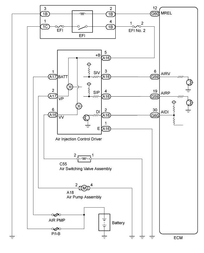
WIRING DIAGRAM
INSPECTION PROCEDURE
Tech Tips
Diagnostic information output by the air injection control driver can be confirmed by connecting an oscilloscope to the diagnostic information terminal of the air injection control driver. Reading the waveform while performing the AIR system forced operation provided in the system check allows the possible trouble areas to be narrowed down.
-
(a) Start the engine and warm it up.
-
(b) Turn the ignition switch off.
-
(c) Connect the intelligent tester to the DLC3.
-
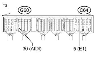
Text in Illustration *a Component with harness connected
(ECM)
(d) Connect oscilloscope probes to the AIDI and E1 terminals of the ECM.
-
(e) Turn the ignition switch to ON and turn the intelligent tester on.
-
(f) Enter the following menus: Powertrain / Engine and ECT / Utility / Secondary Air Injection Check / Manual Mode / AIR PUMP: ON, ASV: CLOSE.
Tech Tips
When Manual Mode is selected, the intelligent tester initialization (atmospheric pressure measurement) is performed automatically. The initialization takes 10 seconds. After the initialization, AIR PUMP and ASV operation can be selected.
-
(g) Start the engine.
-
(h) Perform the AIR system forced operation while the engine is idling.
-
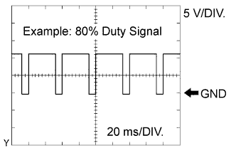
(i) Monitor the air injection control driver voltage output (duty ratio signal).
Measurement Condition Item Content ECM Terminal Name AIDI - E1 Tester Range 5 V/DIV., 20 ms/DIV. Condition Idling -
(j) Turn the ignition switch off.
Note
-
Secondary Air Injection Check only allows technicians to operate the AIR system for a maximum of 5 seconds. Furthermore, the check can only be performed up to 4 times per trip. If the test is repeated, intervals of at least 30 seconds are required between checks. While AIR system operation using the intelligent tester is prohibited, the intelligent tester display indicates the prohibition (Wait or Error).
If Error is displayed on the intelligent tester during the test, stop the engine for 10 minutes, and then try again.
-
Performing Secondary Air Injection Check repeatedly may cause damage to the AIR system. If it is necessary to repeat the check, leave an interval of several minutes between System Check operations to prevent the system from overheating.
-
When performing Secondary Air Injection Check operation after the battery cable has been reconnected, wait for 7 minutes with the ignition switch ON or the engine running.
-
Turn the ignition switch off when the Secondary Air Injection Check operation finishes.
-
| AID Diagnostic Signal Waveform | ECM Command |
DTC (ECM Output) |
Suspected Trouble Area |
|---|---|---|---|
| 100% Duty Ratio 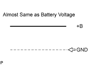 |
Any Secondary Air Injection (AIR) System Operation | P1613 |
|
| 0% Duty Ratio 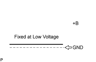 |
AIR System: ON (Air pump ON, Air switching valve ON) | P1613 |
|
| AIR System: OFF (Air pump OFF, Air switching valve OFF) | - | Normal | |
| 20% Duty Ratio 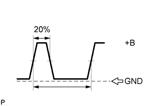 |
Air Pump: ON | P0418 |
|
| Air Pump: OFF | P0418 |
|
|
| 40% Duty Ratio 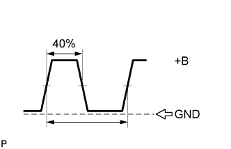 |
Air switching valve: ON | P0412 |
|
| Air switching valve: OFF | P0412 |
|
|
| 80% Duty Ratio 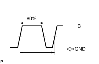 |
AIR System: OFF (Air pump OFF, Air switching valve OFF) | P1613 |
|
| AIR System: ON (Air pump ON, Air switching valve ON) | - | Normal | |
| Other than above (other than 0, 20, 40, 80 or 100% duty) |
- | P1613 |
|
Tech Tips
-
By using the intelligent tester to perform the Secondary Air Injection Check operation in the system check, the air-fuel ratio and the pressure in the secondary air injection system passage can be checked while the secondary air injection system is operating. This helps technicians to troubleshoot the system when it malfunctions.
-
Read freeze frame data using the intelligent tester. Freeze frame data records the engine condition when malfunctions are detected. When troubleshooting, freeze frame data can help determine if the vehicle was moving or stationary, if the engine was warmed up or not, if the air-fuel ratio was lean or rich, and other data from the time the malfunction occurred.
PROCEDURE
-
INSPECT AIR SWITCHING VALVE ASSEMBLY
-
Inspect the air switching valve assembly Click here.
NG 
REPLACE AIR SWITCHING VALVE ASSEMBLY Click here
OK 
-
-
CHECK HARNESS AND CONNECTOR (AIR SWITCHING VALVE ASSEMBLY - BODY GROUND)
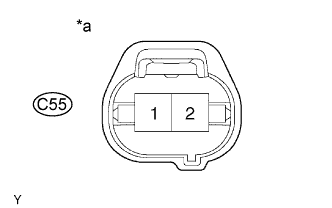
Text in Illustration *a Front view of wire harness connector
(to Air Switching Valve Assembly)
-
Disconnect the air switching valve assembly connector.
-
Measure the resistance according to the value(s) in the table below.
Standard Resistance Tester Connection Condition Specified Condition C55-1 - Body ground Always Below 1 Ω -
Reconnect the air switching valve assembly connector.
NG
REPAIR OR REPLACE HARNESS OR CONNECTOR
OK
-
-
CHECK HARNESS AND CONNECTOR (AIR SWITCHING VALVE ASSEMBLY - AIR INJECTION CONTROL DRIVER)
-
Disconnect the air switching valve assembly connector.
-
Disconnect the air injection control driver connector.
-
Measure the resistance according to the value(s) in the table below.
Standard Resistance (Check for Open) Tester Connection Condition Specified Condition C55-2 - A16-6 (VV) Always Below 1 Ω Standard Resistance (Check for Short) Tester Connection Condition Specified Condition C55-2 or A16-6 (VV) - Body ground Always 10 kΩ or higher -
Reconnect the air switching valve assembly connector.
-
Reconnect the air injection control driver connector.
NG
REPAIR OR REPLACE HARNESS OR CONNECTOR
OK 
REPLACE AIR INJECTION CONTROL DRIVER Click here
-