SFI SYSTEM, Diagnostic DTC:P0335, P0339

| DTC Code | DTC Name |
|---|---|
| P0335 | Crankshaft Position Sensor "A" Circuit |
| P0339 | Crankshaft Position Sensor "A" Circuit Intermittent |
DESCRIPTION
The crankshaft position sensor system consists of a crankshaft position sensor plate and pickup coil. The sensor plate has 34 teeth, with 2 teeth missing for detecting TDC, and is installed on the crankshaft. The crankshaft position sensor generates 34 signals per crankshaft revolution. The ECM determines the cylinder status based on the G2 signals and detects the crankshaft angle and engine speed from the NE signals.
| DTC No. | DTC Detection Condition | Trouble Area |
|---|---|---|
| P0335 | Either condition is met:
|
|
| P0339 | Under conditions (a), (b) and (c), no crankshaft position sensor signal is sent to the ECM for 0.05 seconds or more (1 trip detection logic): (a) The engine speed is 1000 rpm or more. (b) The starter signal is off. (c) 3 seconds or more have elapsed since the starter signal switched from on to off. |
|
-
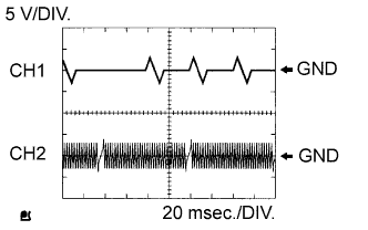
Reference: Inspection using an oscilloscope
Tech Tips
-
The correct waveforms are as shown.
-
G2 is the camshaft position sensor signal, and NE+ is the crankshaft position sensor signal.
-
Grounding failure of the shielded wire may cause noise in the waveforms.
Item Content ECM Terminal Name CH1: G2 - NE-
CH2: NE+ - NE-
Tester Range 5 V/DIV.
20 ms./DIV.
Condition Idling with warm engine
-
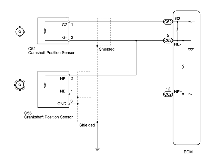
WIRING DIAGRAM
INSPECTION PROCEDURE
-
Before inspecting the crankshaft position sensor, perform the following inspections which concern the camshaft position sensor.
-
Check that the camshaft position sensor connector is securely connected, is not loose, does not rattle, etc.
-
Check that the camshaft position sensor is not loose, does not rattle, etc.
-
Check that the camshaft timing gear is installed properly.
-
Perform the Active Test under the conditions* from the time the noise occurred described by the customer (for example, while driving the vehicle) and check if the noise stops.
Tech Tips
*: Some examples of conditions are idling, racing the engine and driving at full throttle.
Tech Tips
-
Troubleshoot for DTCs P0335 and P0339 first. If the trouble area cannot be determined, there may be a mechanical malfunction.
-
Check the engine speed. The engine speed can be checked by using the intelligent tester. Follow the procedure below:
-
Connect the intelligent tester to the DLC3.
-
Start the engine.
-
Turn the tester on.
-
Enter the following menus: Powertrain / Engine and ECT / Data List / Engine Speed.
-
The engine speed may be indicated as zero despite the crankshaft revolving normally. This is caused by a lack of NE signals from the crankshaft position sensor. Alternatively, the engine speed may be indicated as lower than the actual engine speed if the crankshaft position sensor output voltage is insufficient.
-
Read freeze frame data using the intelligent tester. Freeze frame data records the engine condition when malfunctions are detected. When troubleshooting, freeze frame data can help determine if the vehicle was moving or stationary, if the engine was warmed up or not, if the air fuel ratio was lean or rich, and other data from the time the malfunction occurred.
PROCEDURE
-
READ VALUE USING INTELLIGENT TESTER (ENGINE SPEED)
-
Connect the intelligent tester to the DLC3.
-
Turn the ignition switch to ON.
-
Turn the tester on.
-
Enter the following menus: Powertrain / Engine and ECT / Data List / Engine Speed.
-
Start the engine.
-
Read the values displayed on the tester while the engine is running.
OK Correct values are displayed. Tech Tips
-
To check the engine speed change, display the graph on the tester.
-
If the engine does not start, check the engine speed while cranking.
-
If the engine speed indicated on the tester remains at zero (0), there may be an open or short in the crankshaft position sensor circuit.
-
NG 
INSPECT CRANKSHAFT POSITION SENSOR (RESISTANCE) Click here
OK 
CHECK FOR INTERMITTENT PROBLEMS Click here
-
-
INSPECT CRANKSHAFT POSITION SENSOR (RESISTANCE)
-
Inspect the crankshaft position sensor Click here.
NG 
REPLACE CRANKSHAFT POSITION SENSOR Click here
OK 
-
-
CHECK HARNESS AND CONNECTOR (CRANKSHAFT POSITION SENSOR - ECM)
-
Disconnect the crankshaft position sensor connector.
-
Disconnect the ECM connector.
-
Measure the resistance according to the value(s) in the table below.
Standard Resistance (Check for Open) Tester Connection Condition Specified Condition C53-1 (NE) - C62-12 (NE+) Always Below 1 Ω C53-2 (NE-) - C62-5 (NE-) Always Below 1 Ω Standard Resistance (Check for Short) Tester Connection Condition Specified Condition C53-1 (NE) or C62-12 (NE+) - Body ground Always 10 kΩ or higher C53-2 (NE-) or C62-5 (NE-) - Body ground Always 10 kΩ or higher -
Reconnect the ECM connector.
-
Reconnect the crankshaft position sensor connector.
NG
REPAIR OR REPLACE HARNESS OR CONNECTOR (CRANKSHAFT POSITION SENSOR - ECM)
OK
-
-
CHECK SENSOR INSTALLATION (CRANKSHAFT POSITION SENSOR)
-
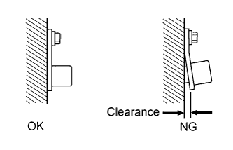
Check the crankshaft position sensor installation condition.
OK Sensor is installed correctly.
NG
SECURELY REINSTALL CRANKSHAFT POSITION SENSOR Click here
OK
-
-
CHECK CRANKSHAFT POSITION SENSOR PLATE (TEETH OF SENSOR PLATE)
-
Check the teeth of the sensor plate.
OK Sensor plate teeth do not have any cracks or deformation.
NG
REPLACE CRANKSHAFT POSITION SENSOR PLATE
OK
REPLACE ECM Click here
-