ECD SYSTEM, Diagnostic DTC:24

| DTC Code | DTC Name |
|---|---|
| 24 | Air Temperature Circuit Malfunction |
DESCRIPTION
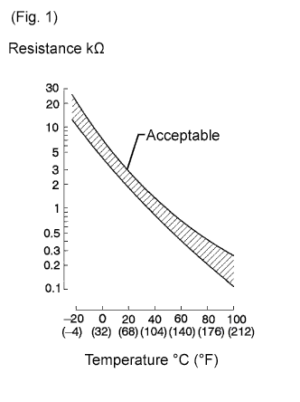
The intake air temperature sensor senses the intake air temperature. A thermistor built into this sensor changes its resistance according to the intake air temperature as shown in the illustration. The resistance value of the intake air temperature sensor is one of the factors used to determine the fuel injection volume.
| DTC No. | DTC Detection Condition | Trouble Area |
|---|---|---|
| 24 | Open or short in the intake air temperature sensor circuit for 0.5 sec. or more. |
|
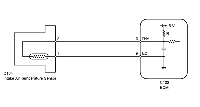
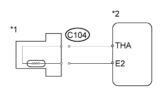
WIRING DIAGRAM
INSPECTION PROCEDURE
Tech Tips
-
If DTCs related to different systems that have terminal E2 as the ground terminal are stored simultaneously, there may be an open circuit between terminal E2 and body ground.
-
Read freeze frame data using the intelligent tester. Freeze frame data records the engine condition when malfunctions are detected. When troubleshooting, freeze frame data can help determine if the vehicle was moving or stationary, if the engine was warmed up or not, and other data from the time the malfunction occurred.
When using intelligent tester:
PROCEDURE
-
READ VALUE USING INTELLIGENT TESTER (INTAKE AIR TEMPERATURE)
-
Connect the intelligent tester to the DLC3.
-
Turn the ignition switch to ON.
-
Enter the following menus: Powertrain / Engine and ECT / Data List / Intake Air.
Result Result Proceed to -40°C (-40°F) A 140°C (284°F) or higher B Value is same as actual engine coolant temperature C Tech Tips
When DTC 24 is stored, the type of malfunction can be determined based on the intake air temperature (see below).
Temperature Displayed Malfunction -40°C (-40°F) Open circuit 140°C (284°F) or higher Short circuit
B 
READ VALUE USING INTELLIGENT TESTER (CHECK FOR SHORT IN WIRE HARNESS) Click here
C 
CHECK FOR INTERMITTENT PROBLEMS Click here
A 
-
-
READ VALUE USING INTELLIGENT TESTER (CHECK FOR OPEN IN WIRE HARNESS)
-
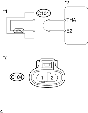
Text in Illustration *1 Intake Air Temperature Sensor *2 ECM *a Front view of wire harness connector
(to Intake Air Temperature Sensor)
Disconnect the intake air temperature sensor connector.
-
Connect terminals 1 and 2 of the intake air temperature sensor harness side connector.
-
Turn the ignition switch to ON.
-
Read the temperature value on the intelligent tester.
OK 140°C (284°F) or higher -
Reconnect the intake air temperature sensor connector.
NG
READ VALUE USING INTELLIGENT TESTER (CHECK FOR OPEN IN ECM) Click here
OK 
REPLACE INTAKE AIR TEMPERATURE SENSOR Click here
-
-
READ VALUE USING INTELLIGENT TESTER (CHECK FOR OPEN IN ECM)
-
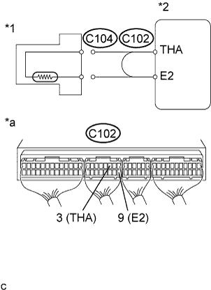
Text in Illustration *1 Intake Air Temperature Sensor *2 ECM *a Component with harness connected
(ECM)
Connect terminals THA and E2 of the ECM connector.
-
Turn the ignition switch to ON.
-
Read the temperature value on the intelligent tester.
OK 140°C (284°F) or higher
NG
REPLACE ECM Click here
OK
REPAIR OR REPLACE HARNESS OR CONNECTOR
-
-
READ VALUE USING INTELLIGENT TESTER (CHECK FOR SHORT IN WIRE HARNESS)
-
Text in Illustration *1 Intake Air Temperature Sensor *2 ECM Disconnect the intake air temperature sensor connector.
-
Turn the ignition switch to ON.
-
Read the temperature value on the intelligent tester.
OK -40°C (-40°F) -
Reconnect the intake air temperature sensor connector.
NG
READ VALUE USING INTELLIGENT TESTER (CHECK FOR SHORT IN ECM) Click here
OK
REPLACE INTAKE AIR TEMPERATURE SENSOR Click here
-
-
READ VALUE USING INTELLIGENT TESTER (CHECK FOR SHORT IN ECM)
-
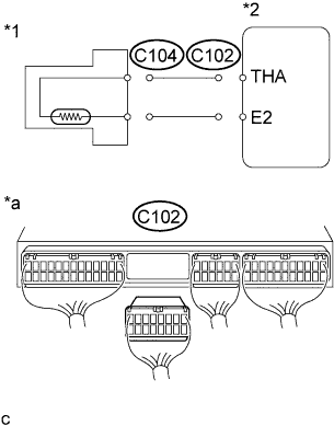
Text in Illustration *1 Intake Air Temperature Sensor *2 ECM *a Rear view of wire harness connector
(to ECM)
Disconnect the ECM connector.
-
Turn the ignition switch to ON.
-
Read the temperature value on the intelligent tester.
OK -40°C (-40°F) -
Reconnect the ECM connector.
NG
REPLACE ECM Click here
OK
REPAIR OR REPLACE HARNESS OR CONNECTOR
-
When not using intelligent tester:
PROCEDURE
-
CHECK ECM
-
Text in Illustration *a Component with harness connected
(ECM)
Turn the ignition switch to ON.
-
Measure the voltage according to the value(s) in the table below.
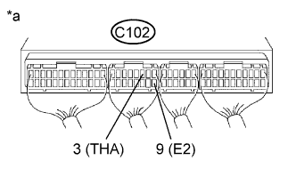
Standard Voltage Tester Connection Condition Specified Condition C102-3 (THA) - C102-9 (E2) 20°C (68°F) 0.2 to 3.8 V C102-3 (THA) - C102-9 (E2) 80°C (176°F) 0.1 to 1.5 V
NG
INSPECT INTAKE AIR TEMPERATURE SENSOR Click here
OK
CHECK FOR INTERMITTENT PROBLEMS Click here
-
-
INSPECT INTAKE AIR TEMPERATURE SENSOR
-
Inspect the intake air temperature sensor Click here.
NG
REPLACE INTAKE AIR TEMPERATURE SENSOR Click here
OK
-
-
CHECK HARNESS AND CONNECTOR (ECM - INTAKE AIR TEMPERATURE SENSOR)
-
Disconnect the intake air temperature sensor connector.
-
Disconnect the ECM connector.
-
Measure the resistance according to the value(s) in the table below.
Standard Resistance (Check for Open) Tester Connection Condition Specified Condition C104-2 - C102-3 (THA) Always Below 1 Ω C104 - C102-9 (E2) Always Below 1 Ω Standard Resistance (Check for Short) Tester Connection Condition Specified Condition C104-2 or C102-3 (THA) - Body ground Always 10 kΩ or higher -
Reconnect the intake air temperature sensor connector.
-
Reconnect the ECM connector.
NG
REPAIR OR REPLACE HARNESS OR CONNECTOR
OK
REPLACE ECM Click here
-