RELAY (w/ DPF) ON-VEHICLE INSPECTION

-
INSPECT STARTER RELAY (ST)
-
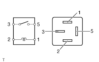
Measure the resistance according to the value(s) in the table below.
Standard Resistance Tester Connection Condition Specified Condition 3 - 5 Battery voltage not applied to terminals 1 and 2 10 kΩ or higher Battery voltage applied to terminals 1 and 2 Below 1 Ω If the result is not as specified, replace the relay.
-
-
INSPECT EDU RELAY (EDU)
-
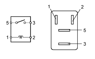
Measure the resistance according to the value(s) in the table below.
Standard Resistance Tester Connection Condition Specified Condition 3 - 5 Battery voltage not applied to terminals 1 and 2 10 kΩ or higher Battery voltage applied to terminals 1 and 2 Below 1 Ω If the result is not as specified, replace the relay.
-
-
INSPECT OIL PRESSURE SWITCHING VALVE RELAY (2ST OIL PRESS)
-
Measure the resistance according to the value(s) in the table below.
Standard Resistance Tester Connection Condition Specified Condition 3 - 5 Battery voltage not applied to terminals 1 and 2 10 kΩ or higher Battery voltage applied to terminals 1 and 2 Below 1 Ω If the result is not as specified, replace the relay.
-
-
INSPECT NO. 1 INTEGRATION RELAY (IG2)
-
Check the IG2 fuse.
-
Measure the resistance according to the value(s) in the table below.
Standard Resistance Tester Connection Condition Specified Condition IG2 fuse Always Below 1 Ω If the result is not as specified, replace the IG2 fuse.
-
-
Check the IG2 relay.
-
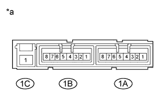
Text in Illustration *a Component without harness connected
(No. 1 Integration Relay)
Measure the resistance according to the value(s) in the table below.
Standard Resistance Tester Connection Condition Specified Condition 1C-1 - 1A-4 Battery voltage not applied to terminals 1A-1 and 1A-3 10 kΩ or higher Battery voltage applied to terminals 1A-1 and 1A-3 Below 1 Ω If the result is not as specified, replace the No. 1 integration relay.
-
-
-
INSPECT NO. 1 INTEGRATION RELAY (EFI)
-
Check the EFI fuse.
-
Measure the resistance according to the value(s) in the table below.
Standard Resistance Tester Connection Condition Specified Condition EFI fuse Always Below 1 Ω If the result is not as specified, replace the EFI fuse.
-
-
Check the EFI relay.
-
Text in Illustration *a Component without harness connected
(No. 1 Integration Relay)
Measure the resistance according to the value(s) in the table below.
Standard Resistance Tester Connection Condition Specified Condition 1C-1 - 1B-4 Battery voltage not applied to terminals 1B-2 and 1B-3 10 kΩ or higher Battery voltage applied to terminals 1B-2 and 1B-3 Below 1 Ω If the result is not as specified, replace the No. 1 integration relay.
-
-
-
INSPECT NO. 1 INTEGRATION RELAY (EFI MAIN)
-
Check the EFI MAIN fuse.
-
Measure the resistance according to the value(s) in the table below.
Standard Resistance Tester Connection Condition Specified Condition EFI MAIN fuse Always Below 1 Ω If the result is not as specified, replace the EFI MAIN fuse.
-
-
Check the EFI MAIN relay.
-
Text in Illustration *a Component without harness connected
(No. 1 Integration Relay)
Measure the resistance according to the value(s) in the table below.
Standard Resistance Tester Connection Condition Specified Condition 1C-1 - 1B-8 Battery voltage not applied to terminals 1B-5 and 1B-7 10 kΩ or higher Battery voltage applied to terminals 1B-5 and 1B-7 Below 1 Ω If the result is not as specified, replace the No. 1 integration relay.
-
-
-
INSPECT MAIN BODY ECU (DRIVER SIDE JUNCTION BLOCK)
Note
The ACC relay and IG1 No. 1 relay are built into the main body ECU (driver side junction block).
-
Inspect the ACC relay.
-
Measure the resistance according to the value(s) in the table below.
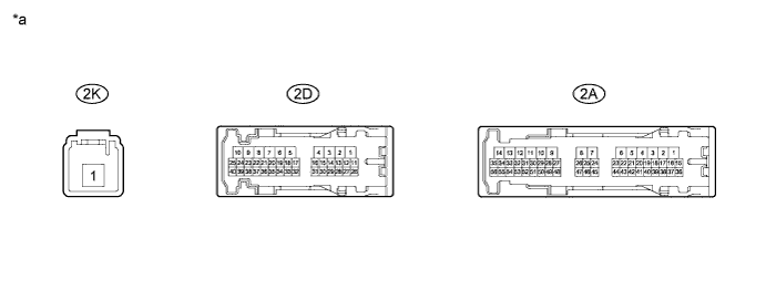
Text in Illustration *a Component without harness connected
(Main Body ECU)
- - Standard Resistance Tester Connection Condition Specified Condition 2D-17 - 2K-1 Battery voltage not applied to terminals 2A-48 and 2D-4 10 kΩ or higher Battery voltage applied to terminals 2A-48 and 2D-4 Below 1 Ω If the result is not as specified, replace the main body ECU.
-
-
Inspect the IG1 No. 1 relay.
-
Measure the resistance according to the value(s) in the table below.
Text in Illustration *a Component without harness connected
(Main Body ECU)
- - Standard Resistance Tester Connection Condition Specified Condition 2A-31 - 2K-1 Battery voltage not applied to terminals 2A-52 and 2D-4 10 kΩ or higher Battery voltage applied to terminals 2A-52 and 2D-4 Below 1 Ω If the result is not as specified, replace the main body ECU.
-
-