CRANKSHAFT POSITION SENSOR (w/ DPF) INSTALLATION

-
INSTALL CRANKSHAFT POSITION SENSOR
-
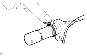
Apply a light coat of engine oil to the O-ring of the crankshaft position sensor.
-
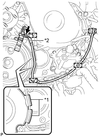
Text in Illustration *1 Protrusion *2 New Clamp Install the crankshaft position sensor with the bolt and attach the 3 wire harness clamps.
- Torque:
- 8.5 N*m { 87 kgf*cm, 75 in.*lbf }
Note
Make sure the crankshaft position sensor wire harness is installed in the position shown in the illustration.
-
Install a new clamp.
Note
Make sure that no portion of the clamp remains in the clamp installation hole. If there is any portion of the clamp remaining, remove it.
-
Connect the crankshaft position sensor connector.
-
-
INSTALL FAN SHROUD
-
Install the fan pulley to the water pump.
-
Install the No. 2 water by-pass hose to the water inlet.
-
Temporarily install the shroud together with the fan with fluid coupling to the water pump with the 4 nuts. Tighten the nuts as much as possible by hand.
-
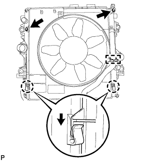
Attach the claws of the shroud to the radiator as shown in the illustration.
-
Install the fan shroud to the radiator with the 2 bolts.
- Torque:
- 5.0 N*m { 51 kgf*cm, 44 in.*lbf }
-
Install the fan and generator V belt Click here.
-
Install the fan with fluid coupling to the water pump with the 4 nuts.
- Torque:
- 23 N*m { 235 kgf*cm, 17 ft.*lbf }
-
Attach the No. 2 water by-pass hose to the clamp on the fan shroud.
-
for Automatic Transmission:
-
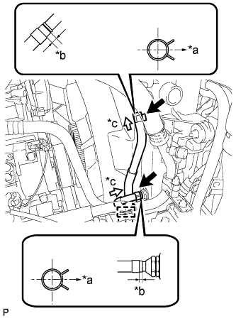
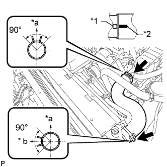
Text in Illustration *a RH Side *b 2.0 to 7.0 mm *c View A Connect the 2 oil cooler hoses.
Tech Tips
-
Position the hose clamps as shown in the illustration.
-
Position the clips so that the distance from the end of the hose is 2.0 to 7.0 mm (0.0787 to 0.275 in.).
-
-
Attach the 2 oil cooler hoses to the clamp on the fan shroud.
-
-
Connect the No. 2 water by-pass hose to the radiator reservoir.
-
Connect the No. 1 water by-pass hose to the fan shroud and attach the 2 clamps.
-
Install the radiator reservoir with the 3 bolts.
- Torque:
- 5.0 N*m { 51 kgf*cm, 44 in.*lbf }
-
-
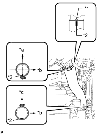
INSTALL NO. 1 RADIATOR HOSE
Text in Illustration *1 Protrusion *2 Paint Mark *a Top *b LH Side
-
Install the radiator hose and attach the clamp.
Tech Tips
Make sure the direction of the hose clamp is as shown in the illustration.
-
-
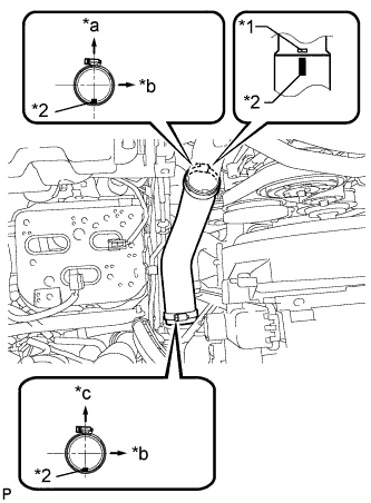
INSTALL INTERCOOLER AIR HOSE
Note
Before installation, remove any oil residue from the inside of the inlet pipe and intercooler.
-
Text in Illustration *1 Embossed Mark *2 Paint Mark *a Rear Side of Vehicle *b LH Side *c Top Align the paint mark of the intercooler air hose with the embossed mark of the intake pipe and install the intercooler air hose.
-
Tighten the 2 clamps.
- Torque:
- 5.0 N*m { 51 kgf*cm, 44 in.*lbf }
-
Connect the vacuum transmitting hose.
-
-
INSTALL NO. 1 AIR HOSE
Note
Before installation, remove any oil residue from the inside of the inlet pipe and intercooler.
-
Text in Illustration *1 Embossed Mark *2 Paint Mark *a Rear Side of Vehicle *b LH Side *c Top Align the paint mark of the No. 1 air hose with the embossed mark of the intercooler and install the No. 1 air hose.
-
Tighten the 2 clamps.
- Torque:
- 5.0 N*m { 51 kgf*cm, 44 in.*lbf }
-
-
INSTALL NO. 3 ENGINE WIRE (for Cold Area Specification Vehicles)
-
Install the 2 nuts to the battery terminals.
- Torque:
- 7.5 N*m { 76 kgf*cm, 66 in.*lbf }
-
Attach the 3 wire harness clamps to the fan shroud.
-
-
ADD ENGINE COOLANT
-
Tighten the radiator drain cock plug by hand.
-
Tighten the cylinder block drain cock plug.
- Torque:
- 8.0 N*m { 82 kgf*cm, 71 in.*lbf }
-
Fill the radiator with TOYOTA Super Long Life Coolant (SLLC) to the B line of the reservoir tank.
Standard Capacity Item Specified Condition for Automatic Transmission w/ Rear Heater 14.9 liters (15.7 US qts, 13.1 Imp. qts) w/o Rear Heater 13.1 liters (13.8 US qts, 11.5 Imp. qts) for Manual Transmission w/ Rear Heater 15.0 liters (15.8 US qts, 13.2 Imp. qts) w/o Rear Heater 13.2 liters (13.9 US qts, 11.6 Imp. qts) Tech Tips
-
TOYOTA vehicles are filled with TOYOTA SLLC at the factory. In order to avoid damage to the engine cooling system and other technical problems, only use TOYOTA SLLC or similar high quality ethylene glycol based non-silicate, non-amine, non-nitrite, non-borate coolant with long-life hybrid organic acid technology (coolant with long-life hybrid organic acid technology consists of a combination of low phosphates and organic acids).
-
Please contact your TOYOTA dealer for further details.
-
for Cold Area Specification Vehicles:
Please contact any authorized TOYOTA dealer or repairer or another duly qualified and equipped professional for further details.
Note
Never use water as a substitute for engine coolant.
-
-
Press the No. 1 and No. 2 inlet and No. 1 and No. 2 outlet radiator hoses several times by hand, and then check the level of the coolant.
If the coolant level drops below the B line, add TOYOTA SLLC to the B line.
-
Install the radiator reservoir cap.
-
Using a wrench, install the vent plug.
- Torque:
- 2.0 N*m { 20 kgf*cm, 18 in.*lbf }
-
Bleed air from the cooling system.
-
Warm up the engine until the thermostat opens. While the thermostat is open, circulate the coolant for several minutes.
-
Maintain the engine speed at a speed between 2500 and 3000 rpm.
-
Press the inlet and outlet radiator hoses several times by hand to bleed air.
CAUTION:
When pressing the radiator hoses:
-
Wear protective gloves.
-
Be careful as the radiator hoses are hot.
-
Keep your hands away from the radiator fan.
-
-
Stop the engine and wait until the coolant cools down to ambient temperature.
CAUTION:
Do not remove the radiator reservoir cap while the engine and radiator are still hot. Pressurized, hot engine coolant and steam may be released and cause serious burns.
-
-
After the coolant cools down, check that the coolant level is at the FULL line.
If the coolant level is below the FULL line, add TOYOTA SLLC to the FULL line.
-
-
INSPECT FOR COOLANT LEAK
Note
Before each inspection, turn the A/C switch off.
CAUTION:
Do not remove the radiator reservoir cap while the engine and radiator are still hot. Pressurized, hot engine coolant and steam may be released and cause serious burns.
-
Fill the radiator with coolant and attach a radiator cap tester.
-
Warm up the engine.
-
Using the radiator cap tester, increase the pressure inside the radiator to 123 kPa (1.3 kgf/cm2, 18 psi), and check that the pressure does not drop.
If the pressure drops, check the hoses, radiator and water pump for leaks. If no external leaks are found, check the heater core, cylinder block and head.
-
-
INSTALL NO. 1 ENGINE UNDER COVER SUB-ASSEMBLY
-
Install the No. 1 engine under cover with the 4 bolts.
- Torque:
- 29 N*m { 296 kgf*cm, 21 ft.*lbf }
-
-
INSTALL FRONT BUMPER LOWER COVER
-
Install the front bumper lower cover with the clip and 5 bolts.
- Torque:
- 8.0 N*m { 82 kgf*cm, 71 in.*lbf }
-
-
INSTALL UPPER RADIATOR SUPPORT SEAL
-
Install the upper radiator support seal with the 13 clips.
-