ECD SYSTEM, Diagnostic DTC:15 (4)

| DTC Code | DTC Name |
|---|---|
| 15 (4) | Throttle Motor Circuit Malfunction |
DESCRIPTION
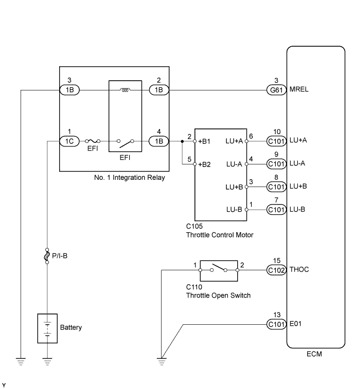
The throttle control motor is operated by the ECM and it opens and closes the throttle valve.
The fully open position of the throttle valve is detected by the throttle open switch mounted on the venturi.
If this DTC is stored, the ECM shuts down the power for the throttle control motor.
| DTC No. | DTC Detection Condition | Trouble Area |
|---|---|---|
| 15 (4) | Open or short in the throttle control motor circuit. |
|
| Open or short in the throttle open switch circuit. |
WIRING DIAGRAM
INSPECTION PROCEDURE
Tech Tips
Read freeze frame data using the intelligent tester. Freeze frame data records the engine condition when malfunctions are detected. When troubleshooting, freeze frame data can help determine if the vehicle was moving or stationary, if the engine was warmed up or not, and other data from the time the malfunction occurred.
PROCEDURE
-
INSPECT DIESEL THROTTLE BODY (THROTTLE OPEN SWITCH)
-
Inspect the throttle open switch Click here.
NG 
REPLACE DIESEL THROTTLE BODY Click here
OK 
-
-
CHECK HARNESS AND CONNECTOR (THROTTLE OPEN SWITCH - ECM AND BODY GROUND)
-
Disconnect the throttle open switch connector.
-
Disconnect the ECM connector.
-
Measure the resistance according to the value(s) in the table below.
Standard Resistance (Check for Open) Tester Connection Condition Specified Condition C110-1 - Body ground Always Below 1 Ω C102-15 (THOC) - C110-2 Always Below 1 Ω Standard Resistance (Check for Short) Tester Connection Condition Specified Condition C102-15 (THOC) or C110-2 - Body ground Always 10 kΩ or higher -
Reconnect the throttle open switch connector.
-
Reconnect the ECM connector.
NG
REPAIR OR REPLACE HARNESS OR CONNECTOR
OK
-
-
CHECK ECM (THROTTLE CONTROL MOTOR CIRCUIT)
-
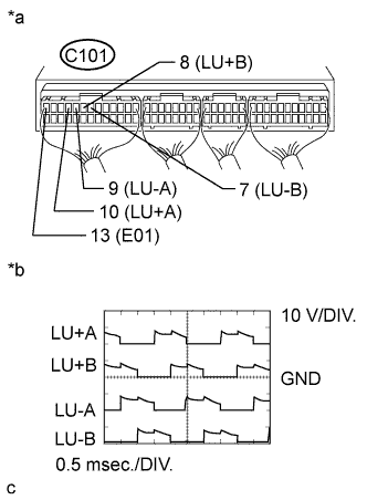
Text in Illustration *a Component with harness connected
(ECM)
*b Signal waveforms During engine racing, check the waveforms according to the value(s) in the table below.
OK Tester Connection Condition Specified Condition C101-10 (LU+A) - C101-13 (E01) Engine racing Correct waveform is as shown C101-9 (LU-A) - C101-13 (E01) Engine racing Correct waveform is as shown C101-8 (LU+B) - C101-13 (E01) Engine racing Correct waveform is as shown C101-7 (LU-B) - C101-13 (E01) Engine racing Correct waveform is as shown
NG 
INSPECT DIESEL THROTTLE BODY (THROTTLE CONTROL MOTOR) Click here
OK 
REPLACE ECM Click here
-
-
INSPECT DIESEL THROTTLE BODY (THROTTLE CONTROL MOTOR)
-
Inspect the throttle control motor Click here.
NG
REPLACE DIESEL THROTTLE BODY Click here
OK
-
-
CHECK HARNESS AND CONNECTOR (THROTTLE CONTROL MOTOR - ECM)
-
Disconnect the throttle control motor connector.
-
Disconnect the ECM connector.
-
Measure the resistance according to the value(s) in the table below.
Standard Resistance (Check for Open) Tester Connection Condition Specified Condition C105-6 (LU+A) - C101-10 (LU+A) Always Below 1 Ω C105-4 (LU-A) - C101-9 (LU-A) Always Below 1 Ω C105-3 (LU+B) - C101-8 (LU+B) Always Below 1 Ω C105-1 (LU-B) - C101-7 (LU-B) Always Below 1 Ω Standard Resistance (Check for Short) Tester Connection Condition Specified Condition C105-6 or C101-10 (LU+A) - Body ground Always 10 kΩ or higher C105-4 or C101-9 (LU-A) - Body ground Always 10 kΩ or higher C105-3 or C101-8 (LU+B) - Body ground Always 10 kΩ or higher C105-1 or C101-7 (LU-B) - Body ground Always 10 kΩ or higher -
Reconnect the throttle control motor connector.
-
Reconnect the ECM connector.
NG
REPAIR OR REPLACE HARNESS OR CONNECTOR
OK
CHECK ECM POWER SOURCE CIRCUIT Click here
-