SFI SYSTEM, Diagnostic DTC:P0412

| DTC Code | DTC Name |
|---|---|
| P0412 | Secondary Air Injection System Switching Valve "A" Circuit |
DESCRIPTION
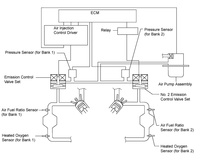
The secondary air injection system injects air into the exhaust port of the cylinder head using an electric air pump, starting when the engine is started cold and operating until the catalyst warms up, in order to promote combustion of unburned fuel and decrease the amount of hydrocarbons (HC) and carbon monoxide (CO) in the exhaust gas.
| DTC No. | DTC Detection Condition | Trouble Area |
|---|---|---|
| P0412 |
|
|
|
|
MONITOR DESCRIPTION
This DTC indicates an open or short circuit in the circuit containing the emission control valve set of the secondary air injection system. The air injection control driver performs diagnosis of the air pump assembly, air switching valve (bank 1) and itself and sends the results of this diagnosis to the ECM as a duty signal. When the ECM receives a signal indicating a malfunction in the air pump assembly, emission control valve set or air injection control driver, it illuminates the MIL and stores a DTC.
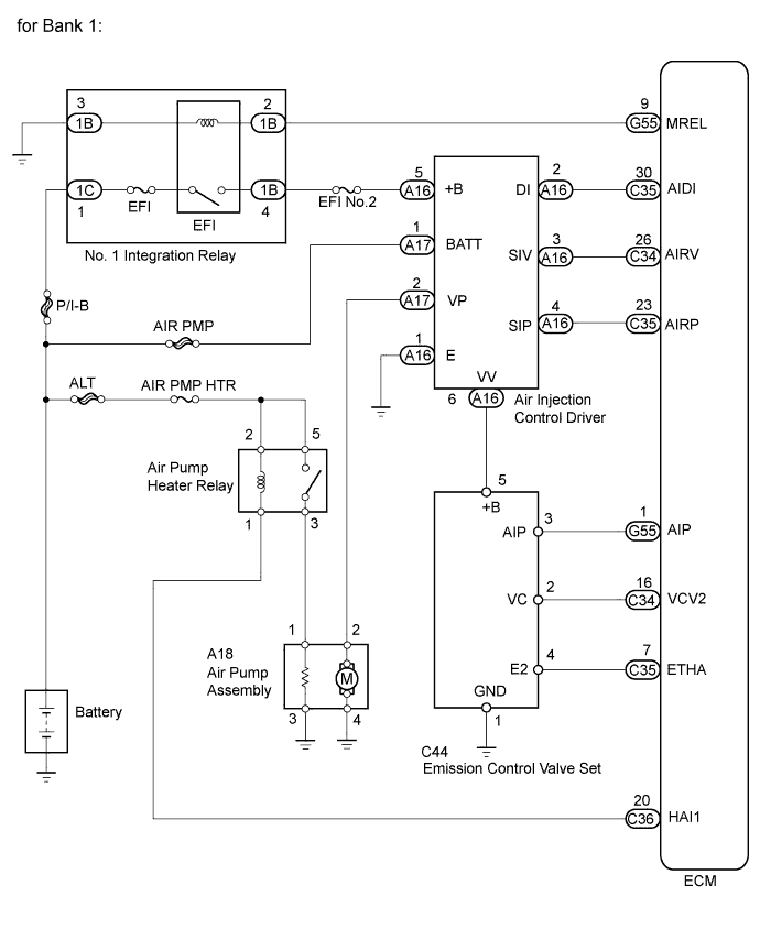
WIRING DIAGRAM
INSPECTION PROCEDURE
Note
Inspect the fuses of circuits related to this system before performing the following inspection procedure.
Tech Tips
-
By using the intelligent tester to perform the Air Injection Check operation in the system check, the air-fuel ratio and the pressure in the secondary air injection system passage can be checked while the secondary air injection system is operating. This helps technicians to troubleshoot the system when it malfunctions.
-
Read freeze frame data using the intelligent tester. Freeze frame data records the engine condition when malfunctions are detected. When troubleshooting, freeze frame data can help determine if the vehicle was moving or stationary, if the engine was warmed up or not, if the air-fuel ratio was lean or rich, and other data from the time the malfunction occurred.
PROCEDURE
-
INSPECT EMISSION CONTROL VALVE SET
-
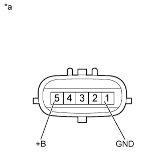
Text in Illustration *a Component without harness connected
(Emission Control Valve Set)
Disconnect the emission control valve set connector.
-
Measure the resistance according to the value(s) in the table below.
Standard Resistance Tester Connection Condition Specified Condition 5 (+B) - 1 (GND) 20°C (68°F) 4.5 to 5.5 Ω -
Reconnect the emission control valve set connector.
NG 
REPLACE EMISSION CONTROL VALVE SET Click here
OK 
-
-
CHECK HARNESS AND CONNECTOR (EMISSION CONTROL VALVE SET - BODY GROUND)
-
Disconnect the emission control valve set connector.
-
Measure the resistance according to the value(s) in the table below.
Standard Resistance Tester Connection Condition Specified Condition C44-1 (GND) - Body ground Always Below 1 Ω -
Reconnect the emission control valve set connector.
NG
REPAIR OR REPLACE HARNESS OR CONNECTOR
OK
-
-
CHECK HARNESS AND CONNECTOR (EMISSION CONTROL VALVE SET - AIR INJECTION CONTROL DRIVER)
-
Disconnect the emission control valve set connector.
-
Disconnect the air injection control driver connector.
-
Measure the resistance according to the value(s) in the table below.
Standard Resistance (Check for Open) Tester Connection Condition Specified Condition C44-5 (+B) - A16-6 (VV) Always Below 1 Ω Standard Resistance (Check for Short) Tester Connection Condition Specified Condition C44-5 (+B) or A16-6 (VV) - Body ground Always 10 kΩ or higher -
Reconnect the emission control valve set connector.
-
Reconnect the air injection control driver connector.
NG
REPAIR OR REPLACE HARNESS OR CONNECTOR
OK 
REPLACE AIR INJECTION CONTROL DRIVER Click here
-