SFI SYSTEM, Diagnostic DTC:P0340, P0342, P0343, P0345, P0347, P0348

| DTC Code | DTC Name |
|---|---|
| P0340 | Camshaft Position Sensor Circuit Malfunction |
| P0342 | Camshaft Position Sensor "A" Circuit Low Input (Bank 1 or Single Sensor) |
| P0343 | Camshaft Position Sensor "A" Circuit High Input (Bank 1 or Single Sensor) |
| P0345 | Camshaft Position Sensor "A" Circuit (Bank 2) |
| P0347 | Camshaft Position Sensor "A" Circuit Low Input (Bank 2) |
| P0348 | Camshaft Position Sensor "A" Circuit High Input (Bank 2) |
DESCRIPTION
The Variable Valve Timing (VVT) sensor (VV1, 2 signal) of the intake camshaft consists of a magnet and MRE (Magnetoresistive Element).
The VVT camshaft drive gear has a sensor plate with 3 teeth on its outer circumference. When the gear rotates, changes occur in the air gaps between the sensor plate and MRE, which affects the magnetic field. As a result, the resistance of the MRE material fluctuates. The VVT sensor converts the gear rotation data to pulse signals, uses the pulse signals to determine the camshaft angle, and sends it to the ECM.
The crankshaft angle sensor plate has 34 teeth. The pickup coil generates 34 signals for each revolution. Based on a combination of the VVT signal and NE signal, the ECM detects the crankshaft angle. Then the ECM uses this data to control fuel injection time and injection timing. Also, based on the NE signal, the ECM detects the engine speed.
| DTC No. | DTC Detection Condition | Trouble Area |
|---|---|---|
| P0340 P0345 |
Either condition is met:
|
|
| P0342 P0347 |
The output voltage of the VVT sensor is below 0.3 V for 4 seconds (1 trip detection logic). | |
| P0343 P0348 |
The output voltage of the VVT sensor is higher than 4.7 V for 4 seconds (1 trip detection logic). |
-
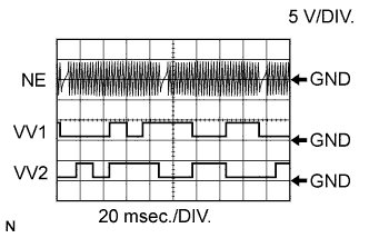
Reference: Inspection using an oscilloscope (VV1, VV2 and NE Signal Waveforms).
Tech Tips
-
The correct waveforms are as shown.
-
VV1+ and VV2+ are the VVT sensor signals, and NE+ is the crankshaft position sensor signal.
-
Grounding failure of the shielded wire may cause noise in the waveforms.
Item Content Terminal VV1+ - VV1-
VV2+ - VV2-
NE+ - NE-
Equipment Setting 5 V/DIV.,
20 msec./DIV.
Condition Cranking or idling -
MONITOR DESCRIPTION
If no signal is transmitted by the VVT sensor despite the engine running, or the rotations of the camshaft and crankshaft are not synchronized, the ECM interprets this as a malfunction of the sensor.
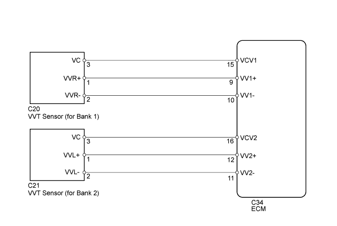
WIRING DIAGRAM
INSPECTION PROCEDURE
Tech Tips
Read freeze frame data using the intelligent tester. Freeze frame data records the engine condition when malfunctions are detected. When troubleshooting, freeze frame data can help determine if the vehicle was moving or stationary, if the engine was warmed up or not, if the air fuel ratio was lean or rich, and other data from the time the malfunction occurred.
PROCEDURE
-
CHECK VVT SENSOR (SENSOR POWER SOURCE)
-
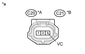
Text in Illustration *A Bank 1 *B Bank 2 *a Front view of wire harness connector
(to VVT Sensor)
Disconnect the VVT sensor connector.
-
Measure the voltage according to the value(s) in the table below.
Standard Voltage Tester Connection Condition Specified Condition C20-3 (VC) - Body ground Always 4.5 to 5.0 V C21-3 (VC) - Body ground Always 4.5 to 5.0 V -
Reconnect the VVT sensor connector.
NG 
REPAIR OR REPLACE HARNESS OR CONNECTOR
OK 
-
-
CHECK HARNESS AND CONNECTOR (VVT SENSOR - ECM)
-
Disconnect the VVT sensor connector.
-
Disconnect the ECM connector.
-
Measure the resistance according to the value(s) in the table below.
Standard Resistance (Check for Open) Tester Connection Condition Specified Condition C20-1 (VVR+) - C34-9 (VV1+) Always Below 1 Ω C20-2 (VVR-) - C34-10 (VV1-) Always Below 1 Ω C21-1 (VVL+) - C34-12 (VV2+) Always Below 1 Ω C21-2 (VVL-) - C34-11 (VV2-) Always Below 1 Ω Standard Resistance (Check for Short) Tester Connection Condition Specified Condition C20-1 (VVR+) or C34-9 (VV1+) - Body ground Always 10 kΩ or higher C20-2 (VVR-) or C34-10 (VV1-) - Body ground Always 10 kΩ or higher C21-1 (VVL+) or C34-12 (VV2+) - Body ground Always 10 kΩ or higher C21-2 (VVL-) or C34-11 (VV2-) - Body ground Always 10 kΩ or higher -
Reconnect the VVT sensor connector.
-
Reconnect the ECM connector.
NG
REPAIR OR REPLACE HARNESS OR CONNECTOR
OK
-
-
CHECK SENSOR INSTALLATION
-
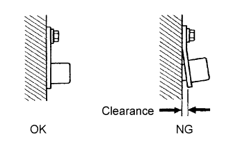
Check the VVT sensor installation.
OK Sensor is installed correctly.
NG
SECURELY REINSTALL SENSOR Click here
OK
-
-
CHECK VALVE TIMING
-
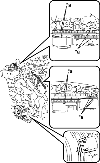
Text in Illustration *a Timing Mark Remove the cylinder head cover sub-assembly RH and LH.
-
Turn the crankshaft to align the matchmarks of the crankshaft.
-
Align the notch of the crankshaft pulley to the "0" position.
-
Check if the timing marks of the camshaft pulley and camshaft bearing cap align.
-
Turn the crankshaft clockwise 360° if the timing marks do not align. Check if they align once again.
OK The timing marks of the camshaft pulley and camshaft bearing cap align when the notch of the crankshaft pulley is in the "0" position. -
Reinstall the cylinder head cover sub-assembly RH and LH.
NG
ADJUST VALVE TIMING Click here
OK
-
-
CHECK CAMSHAFT TIMING GEAR ASSEMBLY (TEETH OF PLATE)
-
Check the teeth of the signal plate.
OK Sensor plate teeth do not have any cracks or deformation.
NG
REPLACE CAMSHAFT TIMING GEAR ASSEMBLY Click here
OK
-
-
REPLACE VVT SENSOR
-
Replace the VVT sensor Click here.
NEXT
-
-
CHECK WHETHER DTC OUTPUT RECURS
-
Connect the intelligent tester to the DLC3.
-
Turn the ignition switch to ON.
-
Turn the tester on.
-
Clear the DTCs Click here.
-
Start the engine.
-
Enter the following menus: Powertrain / Engine and ECT / DTC.
-
Read the DTCs.
Result Result Proceed to No output A P0340, P0342, P0343, P0345, P0347 or P0348 B Tech Tips
If the engine does not start, replace the ECM.
B
REPLACE ECM Click here
A 
END
-