SFI SYSTEM, Diagnostic DTC:P0016, P0018

| DTC Code | DTC Name |
|---|---|
| P0016 | Crankshaft Position - Camshaft Position Correlation (Bank 1 Sensor A) |
| P0018 | Crankshaft Position - Camshaft Position Correlation (Bank 2 Sensor A) |
DESCRIPTION
Refer to DTC P0335 Click here.
| DTC No. | DTC Detection Condition | Trouble Area |
|---|---|---|
| P0016 | Deviations in the crankshaft and camshaft position sensor 1 signals (2 trip detection logic). |
|
| P0018 | Deviations in the crankshaft and camshaft position sensor 2 signals (2 trip detection logic). |
INSPECTION PROCEDURE
Tech Tips
Read freeze frame data using the intelligent tester. Freeze frame data records the engine condition when malfunctions are detected. When troubleshooting, freeze frame data can help determine if the vehicle was moving or stationary, if the engine was warmed up or not, if the air fuel ratio was lean or rich, and other data from the time the malfunction occurred.
PROCEDURE
-
CHECK FOR ANY OTHER DTCS OUTPUT (IN ADDITION TO DTC P0016 OR P0018)
-
Connect the intelligent tester to the DLC3.
-
Turn the ignition switch to ON and turn the tester on.
-
Enter the following menus: Powertrain / Engine and ECT / DTC.
-
Read the DTCs.
Result Result Proceed to P0016 or P0018 A P0016 or P0018 and other DTCs B
B 
GO TO DTC CHART Click here
A 
-
-
PERFORM ACTIVE TEST USING INTELLIGENT TESTER (OPERATE OCV)
-
Connect the intelligent tester to the DLC3.
-
Start the engine and turn the tester on.
-
Warm up the engine.
-
Enter the following menus: Powertrain / Engine and ECT / Active Test / Control the VVT System (Bank 1) or Control the VVT System (Bank 2).
-
Check the engine speed while operating the camshaft timing oil control valve assembly using the tester.
OK Tester Operation Specified Condition OCV OFF Normal engine speed OCV ON Engine idles roughly or stalls soon after camshaft timing oil control valve assembly switched from off to on
NG 
OK
-
-
ADJUST VALVE TIMING
-
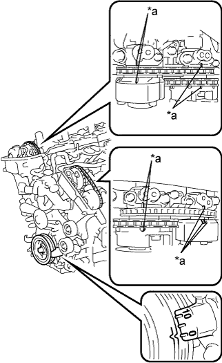
Text in Illustration *a Timing Mark Remove the cylinder head cover sub-assembly RH and LH.
-
Turn the crankshaft to align the matchmarks of the crankshaft.
-
Align the notch of the crankshaft pulley to the "0" position.
-
Check if the timing marks of the camshaft pulley and camshaft bearing cap align.
-
Turn the crankshaft clockwise 360° if the timing marks do not align. Check if they align once again.
OK The timing marks of the camshaft pulley and camshaft bearing cap align when the notch of the crankshaft pulley is in the "0" position. -
Reinstall the cylinder head cover sub-assembly RH and LH.
NEXT
CONFIRM WHETHER MALFUNCTION HAS BEEN SUCCESSFULLY REPAIRED Click here
-
-
INSPECT CAMSHAFT TIMING OIL CONTROL VALVE ASSEMBLY (FOR INTAKE SIDE OF BANK 1, 2)
-
Inspect the camshaft timing oil control valve assembly (for Intake Side of Bank 1, 2) Click here.
NG
REPLACE CAMSHAFT TIMING OIL CONTROL VALVE ASSEMBLY (FOR INTAKE SIDE OF BANK 1, 2) Click here
OK
-
-
INSPECT OIL CONTROL VALVE FILTER AND OIL PIPE
-
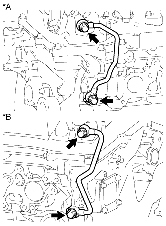
Text in Illustration *A Bank 2 *B Bank 1 Remove the No. 1 oil pipe or No. 2 oil pipe.
-
Remove the oil control valve filter RH or oil control valve filter LH.
-
Check that the oil control valve filter and oil pipe are not clogged.
OK The oil control valve filter and oil pipe are not clogged. -
Reinstall the oil control valve filter RH or oil control valve filter LH.
-
Reinstall the No. 1 oil pipe or No. 2 oil pipe.
NG
REPLACE OIL CONTROL VALVE FILTER OR OIL PIPE
OK
-
-
REPLACE CAMSHAFT TIMING GEAR ASSEMBLY
-
Replace the camshaft timing gear assembly Click here.
NEXT
-
-
CONFIRM WHETHER MALFUNCTION HAS BEEN SUCCESSFULLY REPAIRED
-
In order to clear the ECM learned values for valve timing, disconnect the cable from the negative (-) battery terminal for 1 minute.
-
Connect the cable to the negative (-) battery terminal.
-
Connect the intelligent tester to the DLC3.
-
Turn the ignition switch to ON and turn the tester on.
-
Clear the DTCs Click here.
-
Start the engine and idle it for 5 minutes.
-
Drive the vehicle in an urban area for approximately 10 minutes.
-
Enter the following menus: Powertrain / Engine and ECT / DTC / Pending.
-
Read the DTCs.
OK DTCs are not output.
NG
REPLACE ECM Click here
OK 
END
-